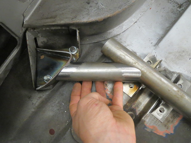
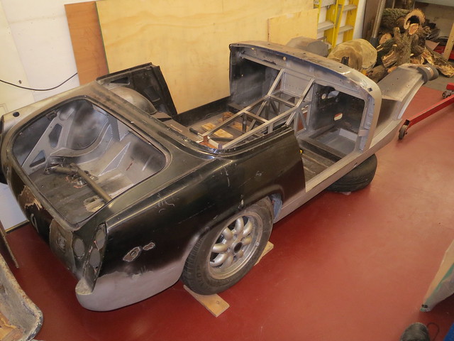
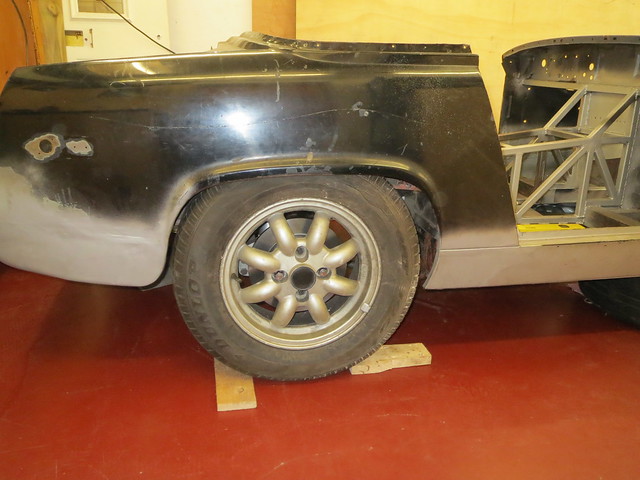
With the rear suspension complete, although I am still to check the
wheel clearance, it was time to make a start on the front end. But first
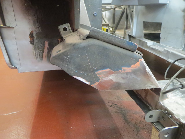
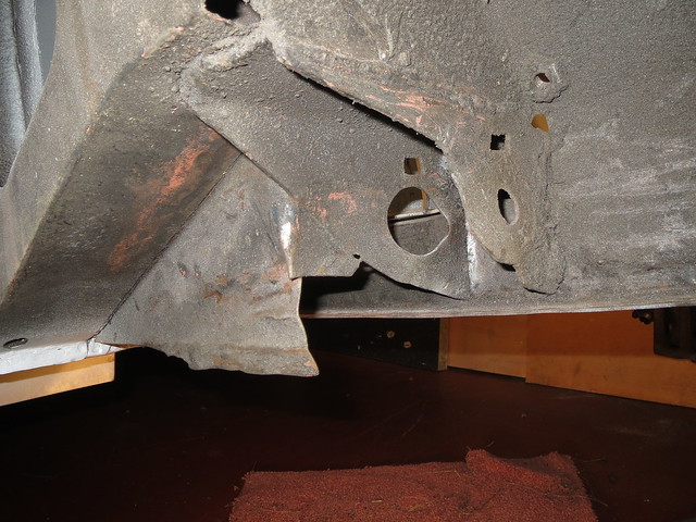
I needed to cut the existing brackets and supports back to match what I
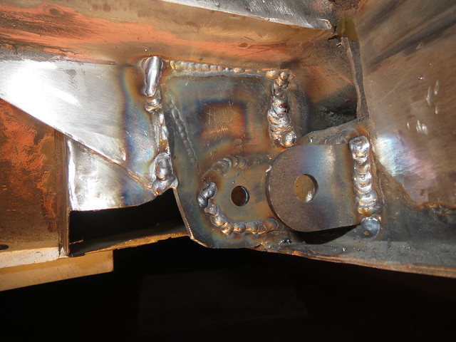
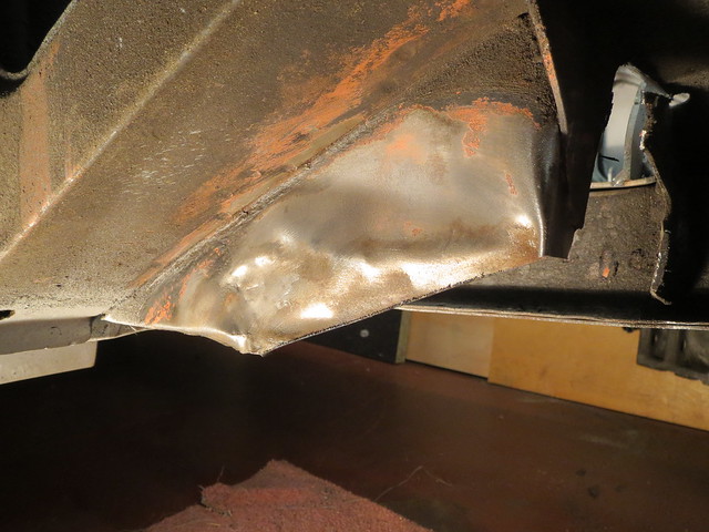
had already done on the LHS of the car. The RHS looked like this some
time ago:
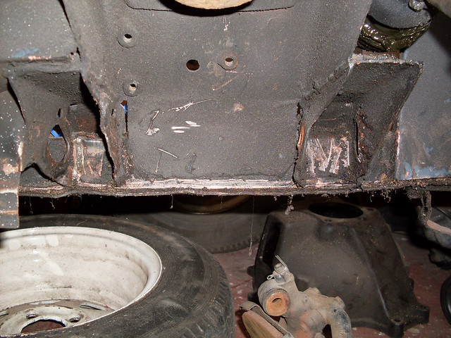
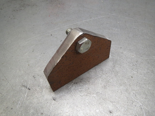
I
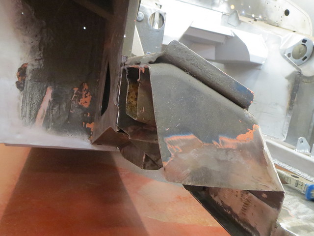
started off cutting back the front bracket and it's supporting plate
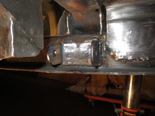
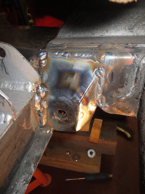
back. But I soon ran into an unexpected, but minor, problem. Part way
through cutting the bracket back, I found that it was both cracked
through above the chassis rail, and on the verge of removing itself from
the rail altogether.
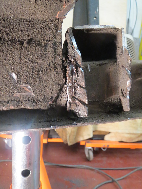
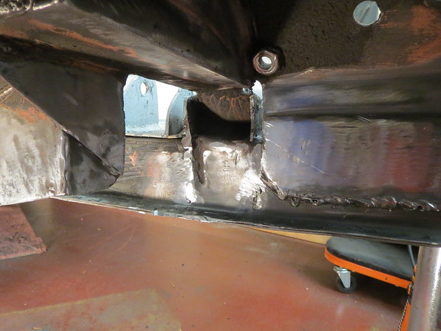
Thankfully,
the tear is almost on top of one of the inner webs that I fitted when I
straightened the rails so welding it up was nice and easy.
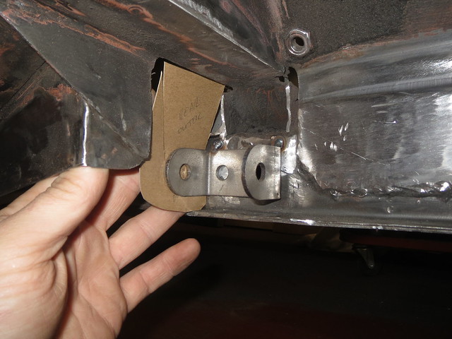
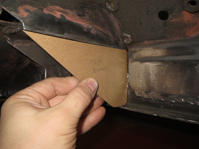
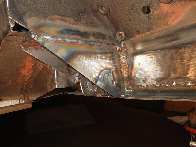
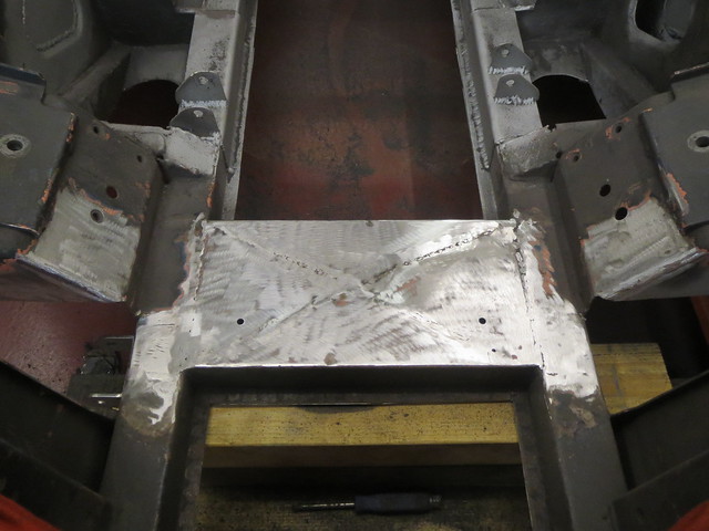
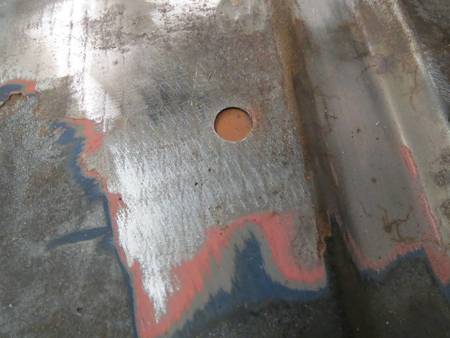
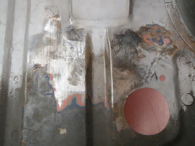
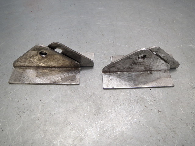
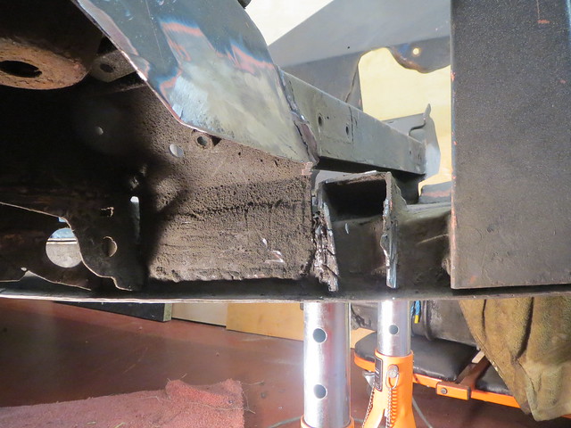
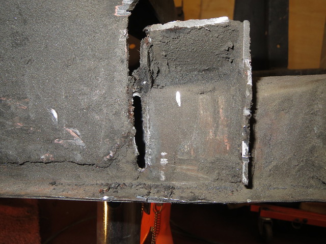
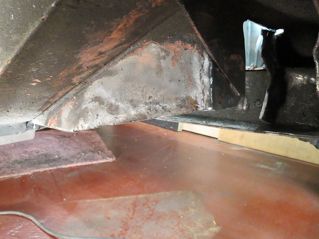
The rear half of things was next. It started off looking a bit worse for wear:
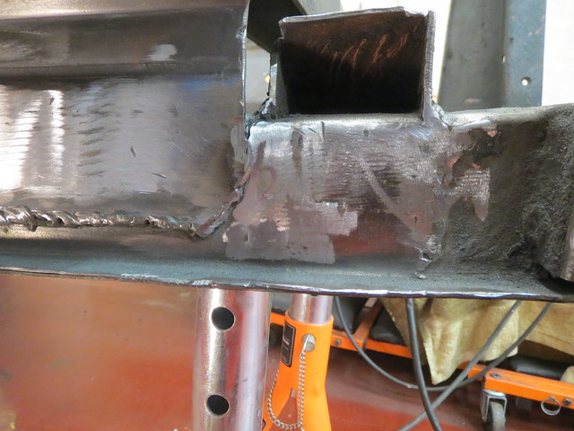
Once
I'd cut back most of the unwanted sections, and given it all a clean up
there was the rippled section left to flatten. The remaining bits were
then cut back as far as I could get them:
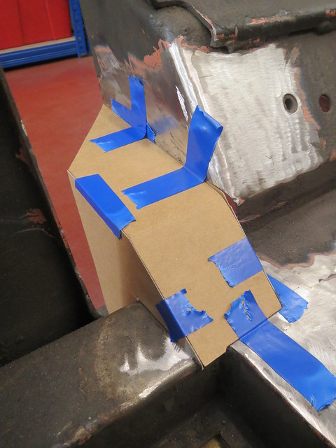
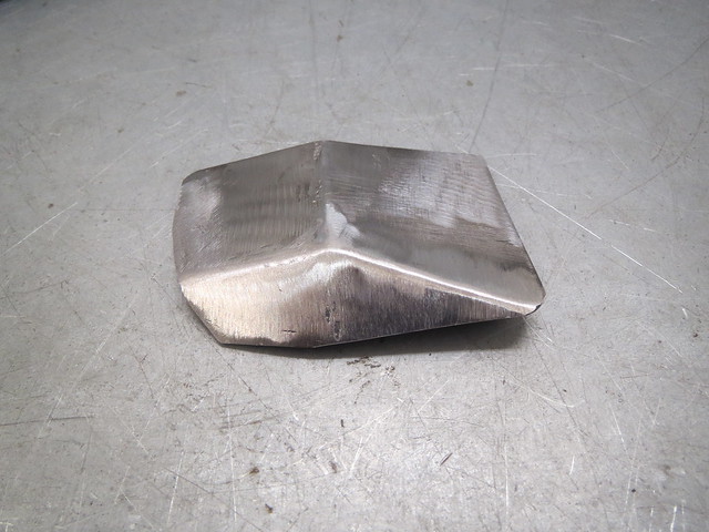
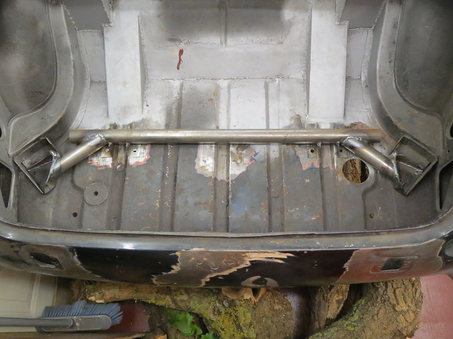
So
now I had a good clean base for the suspension. This side will be built
up and checked as thoroughly as I know how to before using it to make a
jig for both of the suspension arms. That way I can ensure it's all
even, and should I ever bin it I can make new ones easily. Before I
could start with the brackets on the car, I wanted to make sure the hubs
and wheel fitted together ok. They're also needed to measure the length
needed for the lower arm, as it will be determined by the track width.
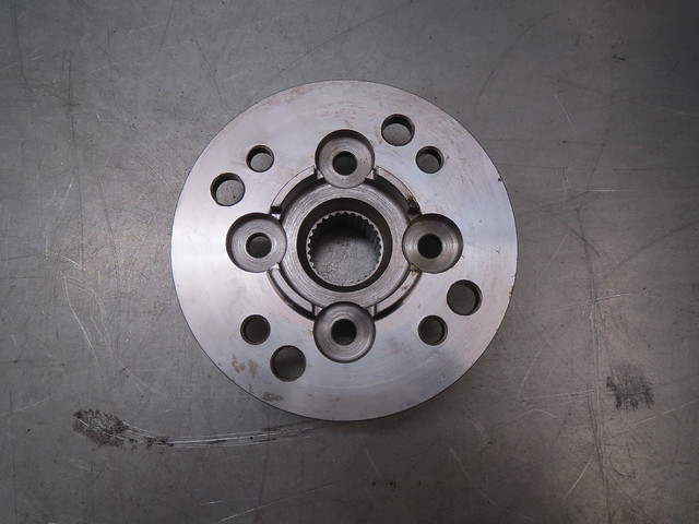
The
front end is based on the uprights/hubs of a classic mini, but using
the later Metro drive flanges as they're bigger. The usual PCD of a
mini/metro is 4 x 4", ie 4 wheel studs spaced evenly on a 4" circle. My
rear suspension, and wheels, use the Ford pattern of 4 x 108mm. Small
differences can be taken up with special bolts, but the 6.4mm difference
I have is too much for that. So the only real option is to re-drill the
drive flange to suit the wider spacing. This isn't something I was
willing to attempt, as the holes must be bang on and very closely sized
to the splines on the new studs. But thankfully there's a local place
that was happy to alter them for me, as well as trim my CV joints down
to save some extra weight.
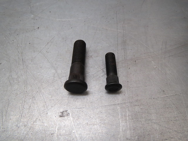
The
next thing to do was to fit the new studs. The mini studs are 3/8"
where as the new ones are M12, so quite a bit bigger. Which is a good
thing as the Sprite will have a top speed well in excess of a mini! The
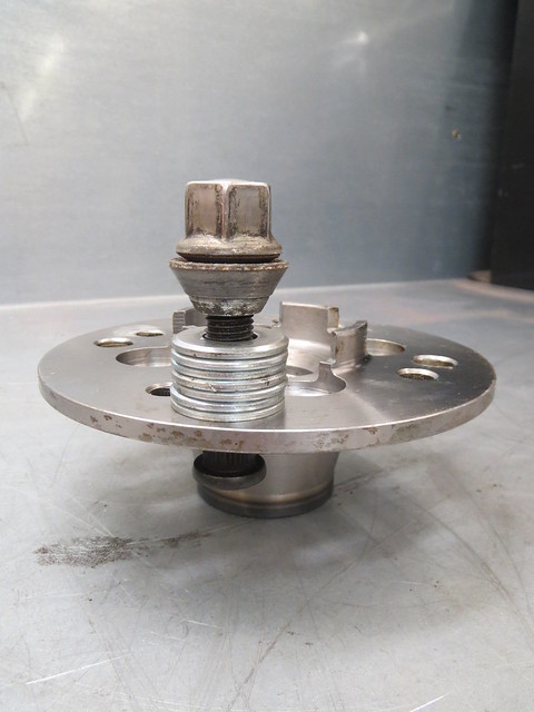
easiest way I know of to fit studs is to go find a man with a press,
but by this time all the local garages were shut, so I used a more
manual method using a spare wheel nut and some washers. As the nut is
turned the stud is drawn into the flange.
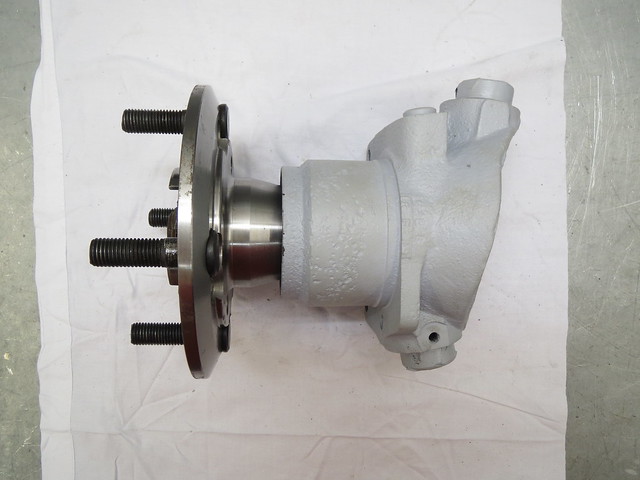
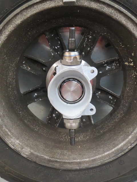
With
all eight studs fitted, bearings were fitted to the upright. These are
just plain ball bearings for now, as I'll be using the better, but more
expensive, taper roller bearings for the final build up. The same is
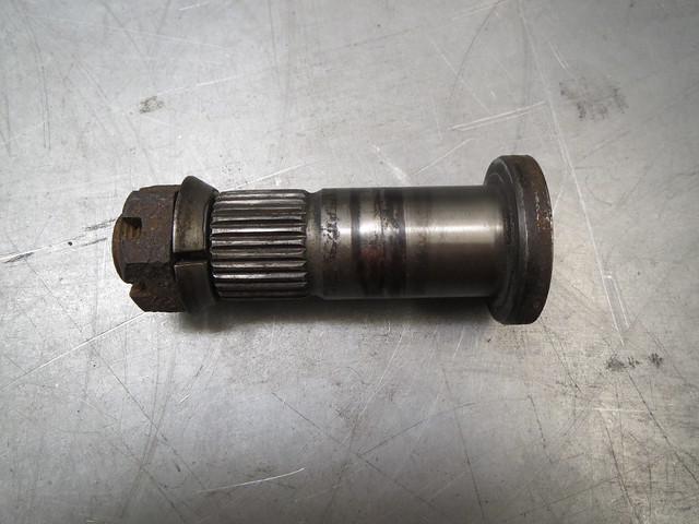
true of the ball joints, cheapo versions for now. The axle stub then
goes in before putting the drive flange on. It looks a little long once
assembled as the brake discs sits behind the drive flange. And as I'll
be using 10.75" MGB discs they'll be an adaptor to match the threads
that sits between the flange and disc. I'm using the hubs swapped side
to side, as a mini has it's steering rack behind the wheels, where as
the Sprite has it in front. This stops the brakes and steering trying to
share the same space, but has no effect on the suspension itself.
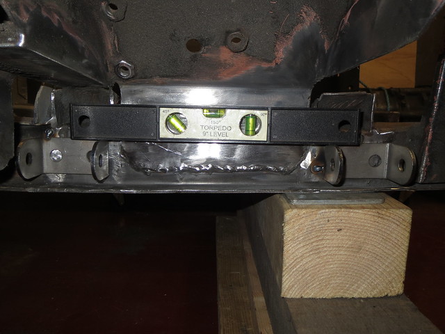
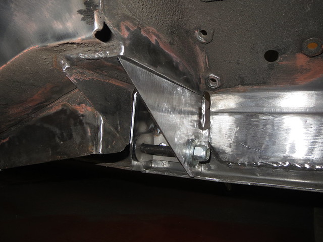
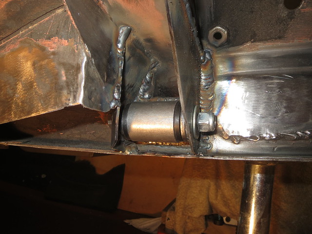
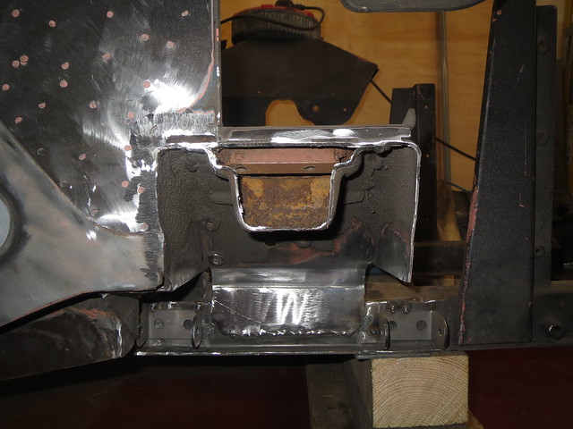
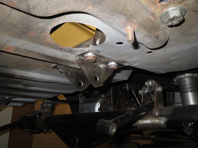
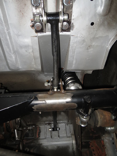
So
the front uprights were now fitted and I was happy with that end of
things. And that meant the last thing to do today was to spend a while
levelling the suspension brackets and tacking them in place. I say
levelling, as the front chassis rails kick upwards on a Sprite by 1" to
give extra castor. However, my set up won't need that so the brackets
are level to the ground and not the rails, hence why they look wonky.
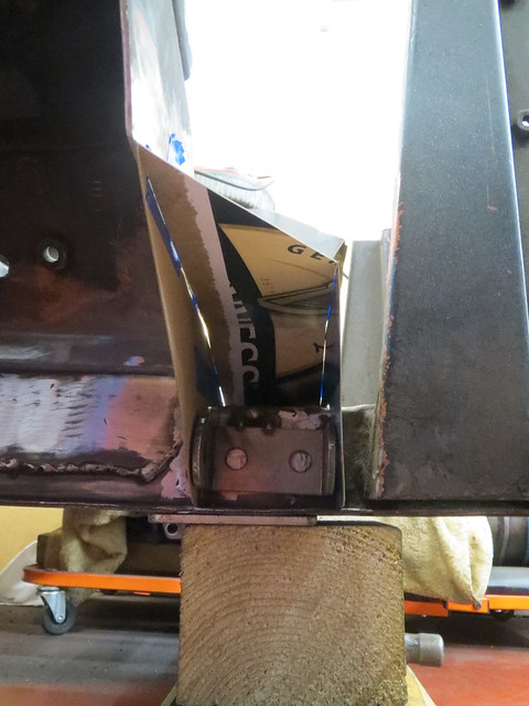
The brackets are also fitted as wide as possible, given the webs hidden
inside the chassis rail. This gives the strongest possible base for the
lower arm without completely re-building the front end again.