Due to a change in domestic situations, the Workshop will be closing in the near future and getting a new owner. My projects and work will still continue, but it may well see a change in direct to house renovation! Just got to get one house sold and then start the search for my own place.
Thanks for following, and there will be more to follow. I just don't know when yet!
Sunday, 26 April 2015
Friday, 6 March 2015
Wishbone fitting
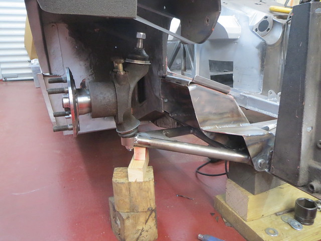
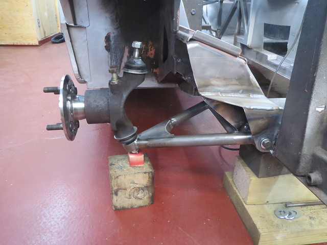
Since the Mk 1 wishbone only sort of fits, I needed to cut the chassis support brackets back a bit to allow it room to move. Thankfully, this won't take long. The idea is to loosely follow the curve of the chassis bracket before cutting back to the existing support panel edge. This was the first go:
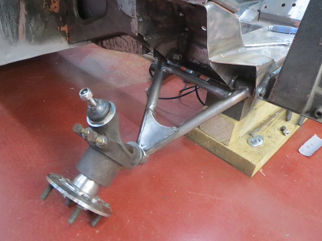
This turned out to be almost enough, but I needed to trim a little further back as I hadn't allowed enough for the main tubes to clear. Once I had done so, the wishbone and hub now go this far up. This should be more than enough for what I need. I doubt I can find a coil over with as much travel as this.
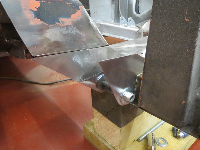
Whilst I was just about out of time to play today, I wanted to see what things looked like with the wheel in place. As the ball joints are new, and therefore stiff, the wheel isn't heavy enough to pull the hub over and it will sit in place.

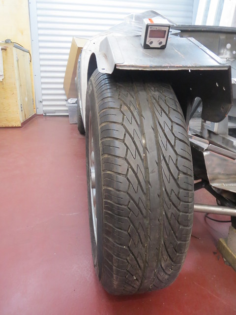
As hoped, the wishbone sits about flat for now. It will be hard to tell for certain until I get both sides done and the car at something like kerb weight, as I don't know how much the tyre will compress by. It also looks like the overall width is about right too. It might be a bit wider, but with the 185 section tyres on et35 wheels that's no surprise. I had thought the upper ball joint would sit lower than it does. This isn't a bad thing as it happens, as it gives me more options for mounting the top wishbone in a more sensible place. I was thinking it would need to be mounted inside the suspension tower, but it now looks like I can mount it on top somewhere. This should allow me a bolt on mount, which is much, much easier than cutting into the tower and main A frame.
Thursday, 5 March 2015
Mk1 wishbone complete!
Since yesterday was quiet at work, I got home a bit early and managed some garage time.
The first thing to do was to get the second main tube cut and shaped:
This was then tacked in place before removing from the jig for welding. Once cooled, it was put back in the jig to check for any distortion. Somehow, I don't really have any so far, with just the arm closing in by 1-2mm.
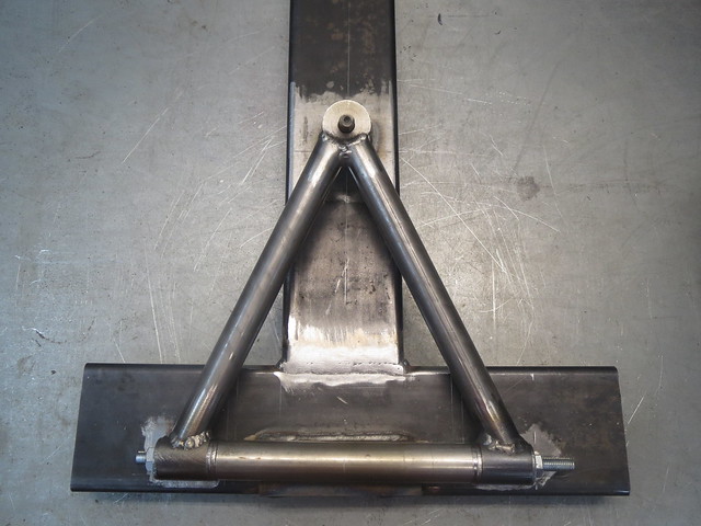
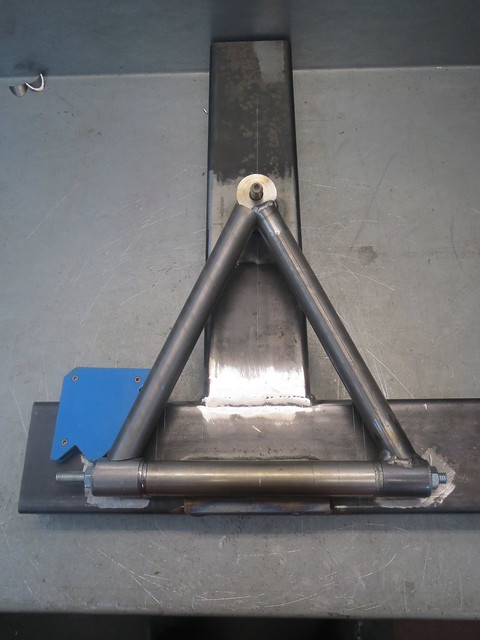
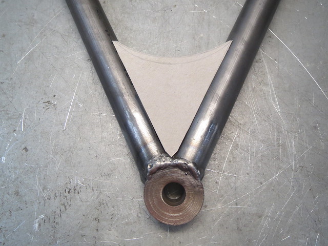
The next part is a cross brace to stop the arm trying to open/close under load. This is made of 3/4" tube.
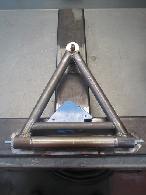
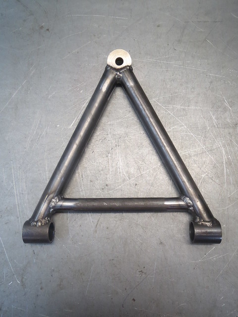
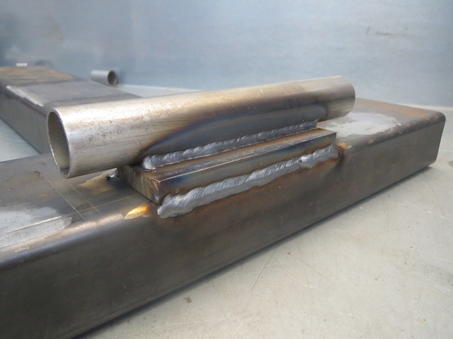
For the basic frame of the wishbone, that's it! However, I still need somewhere to mount a coil over. That somewhere gives a few options. One is a thick-ish plate between the tubes, another is a double gusset thing that looks like a box between the arms, and another is a set up that allows a long bolt to pass through both main tubes using short sections of tube let into the main ones. I prefer the middle option; boxing in the end of the wishbone.


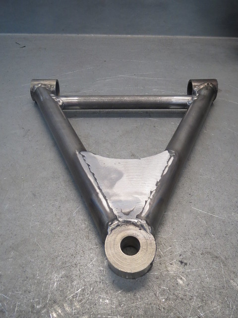
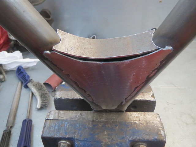
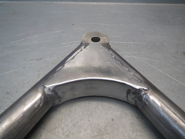
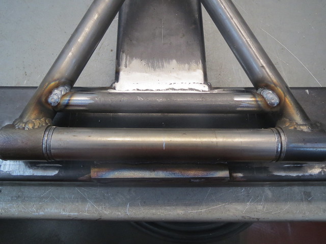
Whilst I wouldn't normally grind the welds back flat, for this piece I need a flat surface for when I get round to fitting the coil over bracket. With the wishbone complete for now, I wanted to see what it looks like on the car! This meant putting the nylon bushes back in and their inner crush tubes. As they're supplied over length, I can't get all the washers into the chassis brackets as yet, but with both outer ones in place, the wishbone is plenty steady enough for now and still falls on the pivots under it's own weight.
Can anyone spot the school boy error I've made?!
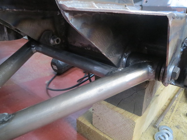
Yup, I got carried away making the wishbone and didn't bother checking the cross brace cleared. However, to do it's job, it needs to be pretty much where I've welded it in. So it looks like I'll have to trim the support brackets back a bit to allow the wishbone to move. Currently it doesn't even get to ride height. Overall though, I'm rather pleased with my Mk1 wishbone!!
The first thing to do was to get the second main tube cut and shaped:
This was then tacked in place before removing from the jig for welding. Once cooled, it was put back in the jig to check for any distortion. Somehow, I don't really have any so far, with just the arm closing in by 1-2mm.
The next part is a cross brace to stop the arm trying to open/close under load. This is made of 3/4" tube.
For the basic frame of the wishbone, that's it! However, I still need somewhere to mount a coil over. That somewhere gives a few options. One is a thick-ish plate between the tubes, another is a double gusset thing that looks like a box between the arms, and another is a set up that allows a long bolt to pass through both main tubes using short sections of tube let into the main ones. I prefer the middle option; boxing in the end of the wishbone.
Whilst I wouldn't normally grind the welds back flat, for this piece I need a flat surface for when I get round to fitting the coil over bracket. With the wishbone complete for now, I wanted to see what it looks like on the car! This meant putting the nylon bushes back in and their inner crush tubes. As they're supplied over length, I can't get all the washers into the chassis brackets as yet, but with both outer ones in place, the wishbone is plenty steady enough for now and still falls on the pivots under it's own weight.
Can anyone spot the school boy error I've made?!
Yup, I got carried away making the wishbone and didn't bother checking the cross brace cleared. However, to do it's job, it needs to be pretty much where I've welded it in. So it looks like I'll have to trim the support brackets back a bit to allow the wishbone to move. Currently it doesn't even get to ride height. Overall though, I'm rather pleased with my Mk1 wishbone!!
Tuesday, 3 March 2015
Finishing the jig and starting the wishbone
I've been spending some time looking into jig building and how to do
things for the best. Ideally, I'd like to make a jig that would allow me
to fully weld all the joints in place, but I'm not sure I can make such
a jig with enough accuracy, or if it's practical with the ball joint
pin I need to add. So I've decided to alter the frame I have to better
suit what I need. And that meant cutting off the existing brackets and
welding in a support tube so I can clamp the pivot tubes in places. This
has the advantage of not needing the nylon bushes to be in place, as
the heat of even tack welding would melt them a little. They're also a
bugger to remove without trashing them. Whilst I was there, I raised the
tube off the frame a little to help with clearances.
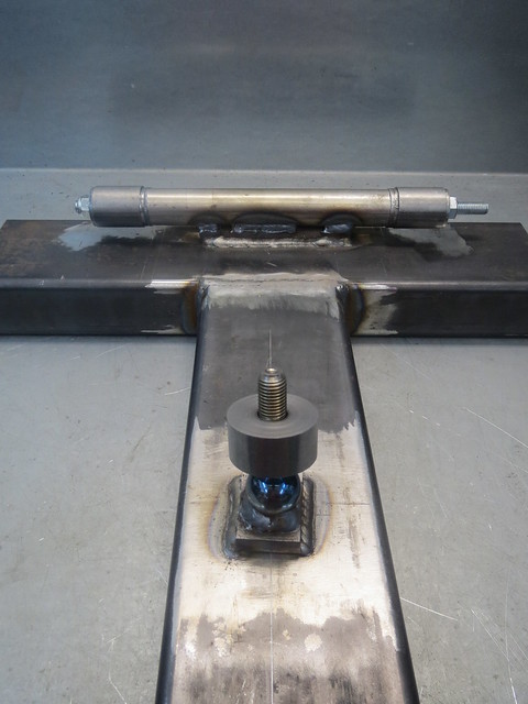
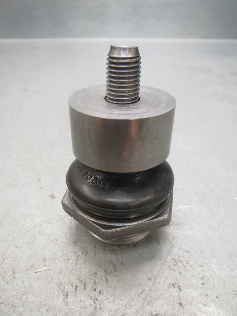
The next thing to do was to double check all the measurements I could and then to line up and weld in the ball joint pin. This too was raised off the frame to maintain the line between the centre of the pivot tubes and the centre of the ball joint ball. These are the points that matter as they're the ones that everything revolves around, regardless of the shape of the rest of the wishbone. The hub measures as having a 18.1 degree angle against the hub face, and I'm quite happy with the 0.1 degree difference! And whilst this might sound a bit geeky, I love the colours on the polished ball!!

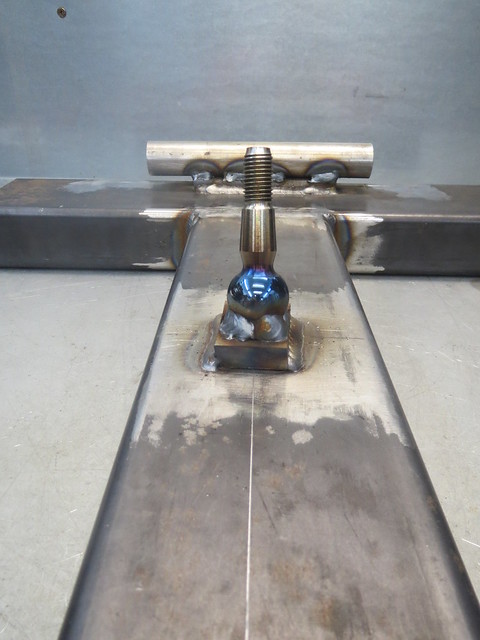
The idea is that the pivot tubes and the ball joint bush are then set in place so I have a template to cut the main tubes for. As the lower wishbone aren't handed, this jog will do for both sides.
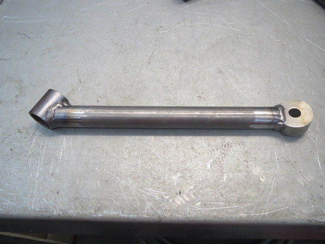
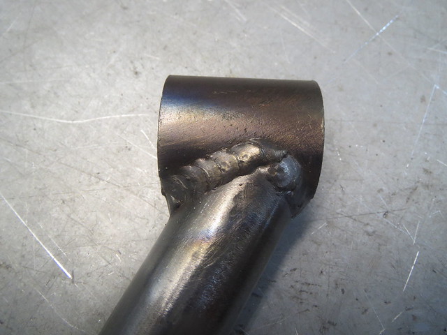
Cutting the tubes to match the pivots is the easy bit, but fitting the other end to the bush I found a bit harder, as the bush doesn't sit square to the wishbone, and needs it's lower edge to be level with the tube so it doesn't block the ball joint. It has to be offset to centre the joint and give the maximum movement without binding. Cutting this one tube took me about an hour! I do expect the second one to go quicker though. I also found that trying to set both pivot tubes and all 6 washers at once is impossible, so I left one side out.

With the tube tacked in place, I decided it was best to remove it from the jig so I could fully weld it. The bush end needs doing at this point anyway, as I can't get at it fully once the other main tube is in place.

The next thing to do was to double check all the measurements I could and then to line up and weld in the ball joint pin. This too was raised off the frame to maintain the line between the centre of the pivot tubes and the centre of the ball joint ball. These are the points that matter as they're the ones that everything revolves around, regardless of the shape of the rest of the wishbone. The hub measures as having a 18.1 degree angle against the hub face, and I'm quite happy with the 0.1 degree difference! And whilst this might sound a bit geeky, I love the colours on the polished ball!!
The idea is that the pivot tubes and the ball joint bush are then set in place so I have a template to cut the main tubes for. As the lower wishbone aren't handed, this jog will do for both sides.
Cutting the tubes to match the pivots is the easy bit, but fitting the other end to the bush I found a bit harder, as the bush doesn't sit square to the wishbone, and needs it's lower edge to be level with the tube so it doesn't block the ball joint. It has to be offset to centre the joint and give the maximum movement without binding. Cutting this one tube took me about an hour! I do expect the second one to go quicker though. I also found that trying to set both pivot tubes and all 6 washers at once is impossible, so I left one side out.
With the tube tacked in place, I decided it was best to remove it from the jig so I could fully weld it. The bush end needs doing at this point anyway, as I can't get at it fully once the other main tube is in place.
Tuesday, 24 February 2015
Bushes machined, new type of hubs arrived!
Got my parts in the post from Red 7 Autoengineering. I had 8 bushes machined so I can cock a
complete set up of wishbones up and still have enough left over for another go. £65 for them all,
posted, and I'm well pleased with them.

So I can make a start on lining things up for the jig and the first version of the lower wishbone. There will be an inner end bracing tube and an outer end gusset to spread the load and give me somewhere to stick the coil over.

Tuesday, 3 February 2015
The beginnings of a lower wishbone
With a few hours to spare today, I managed to get out and get a little more done in the garage. Most of what I've been doing of late has been research into the front suspension. Things like a direct hub to hub width are hard to find, as they vary with suspension travel. But this is a measurement that I need an idea of to start lining up for my wishbones. I have finally managed to figure out something pretty close to what I need, so I could start setting up at last. And it turns out that the BMC/Austin designers only worked in nice even imperial measurements.

So I now need to make a start on a 10" deep A frame wishbone. The plan is to make a jig to allow me to mock everything up and alter it easily as I discover problems that I haven't foreseen. The basis of the jig I have had lying about for ages, waiting for me to get to this point at long last. It is based on large box section, welded into a T shape. The plan is that I will have the upper wishbone jig on one side, and the lower on the other.


So I now need to make a start on a 10" deep A frame wishbone. The plan is to make a jig to allow me to mock everything up and alter it easily as I discover problems that I haven't foreseen. The basis of the jig I have had lying about for ages, waiting for me to get to this point at long last. It is based on large box section, welded into a T shape. The plan is that I will have the upper wishbone jig on one side, and the lower on the other.
The main issue I face now is that I need to find somewhere to machine me the tapered steel end pieces I need for the outer joint. Without those accurately tack welded in place, I can't make a start the wishbone tubes. These will be the same 1" tubing that the rear A frame is made from as I have loads of it and it's strong as hell.
Thursday, 22 January 2015
Some minor progress after a bit of a lay off
I've just realised it's been two months since I last updated this
thread, but that's mainly because I've been too busy to devote any real
time to the Sprite. I have managed to get a little more done, but not a
lot.
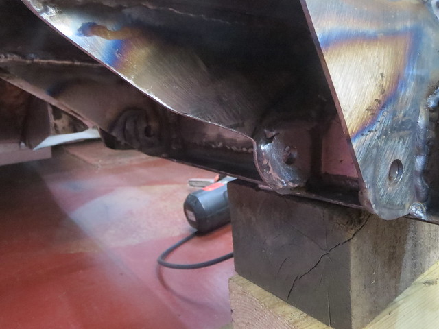
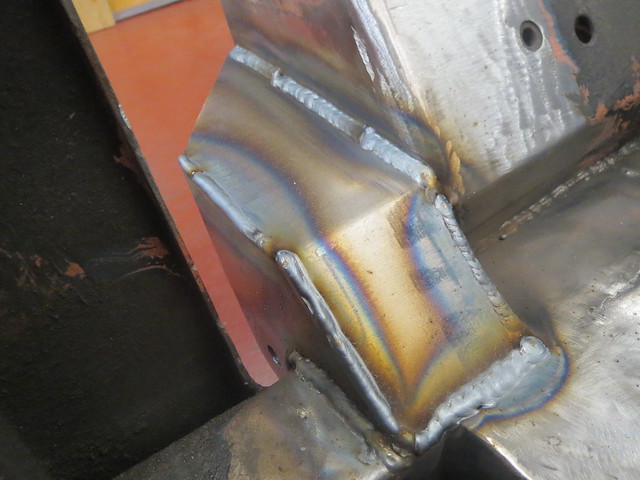
I was planning on getting the rear mount tidied up and painted, but I wanted to make a little more visible progress so I set to with the front mount. Having made the templates previously, this was mainly a job of transferring them to 2mm sheet. Due to the way I'm making these mounts, the first section is the one designed to feed the loads into the chassis rail. The other sections are there to both support the first one, as well as brace the suspension tower and the rails to each other. The first job was to weld the front mount itself in place:
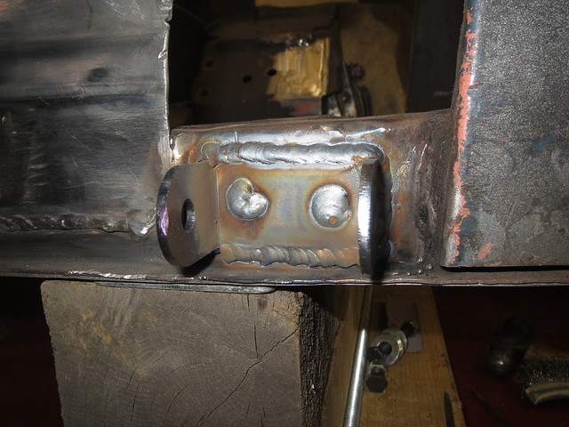
This then lets me make the final adjustments to the steel sheet sections, one of which needed a small section welding to the back to close off the gap to the suspension tower.
These two bits were welded in so I could make sure the top section fitted. Whilst I could have re-made it to close the gap on the right hand side down a little, I didn't think it worth the bother.
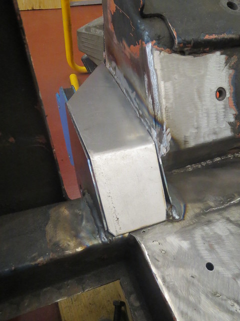
As before, all the sections are seam welded on both sides.
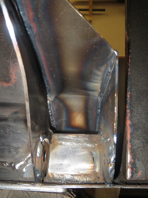
I do still have the weld on the rear support to the chassis rail underneath the suspension tower to do to finish this mount off. But I was getting a crampy back from being curled up on the floor, so I left that weld for another day. To give me something else to do, I decided to cut the coil spring mount out. There was just too much rust showing so it had to come out. Just a shame it took me hours to do, as it's held in with a good few spot welds as well as some little seam welds which I couldn't get to to cut out with the grinder so it was a tedious process.
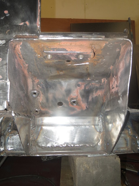
I am now seriously contemplating some form of brace to go in the box, as that tower will be taking the loads from both the coil over and the top suspension arm, so it can not flex. As it is, the box is just too big/too open for my liking. I my just put the cover plate back a little inside the tower and then brace forwards as it'll be easier to fabricate than trying to make a frame to go behind a cover plate.
I was planning on getting the rear mount tidied up and painted, but I wanted to make a little more visible progress so I set to with the front mount. Having made the templates previously, this was mainly a job of transferring them to 2mm sheet. Due to the way I'm making these mounts, the first section is the one designed to feed the loads into the chassis rail. The other sections are there to both support the first one, as well as brace the suspension tower and the rails to each other. The first job was to weld the front mount itself in place:
This then lets me make the final adjustments to the steel sheet sections, one of which needed a small section welding to the back to close off the gap to the suspension tower.
These two bits were welded in so I could make sure the top section fitted. Whilst I could have re-made it to close the gap on the right hand side down a little, I didn't think it worth the bother.
As before, all the sections are seam welded on both sides.
I do still have the weld on the rear support to the chassis rail underneath the suspension tower to do to finish this mount off. But I was getting a crampy back from being curled up on the floor, so I left that weld for another day. To give me something else to do, I decided to cut the coil spring mount out. There was just too much rust showing so it had to come out. Just a shame it took me hours to do, as it's held in with a good few spot welds as well as some little seam welds which I couldn't get to to cut out with the grinder so it was a tedious process.
I am now seriously contemplating some form of brace to go in the box, as that tower will be taking the loads from both the coil over and the top suspension arm, so it can not flex. As it is, the box is just too big/too open for my liking. I my just put the cover plate back a little inside the tower and then brace forwards as it'll be easier to fabricate than trying to make a frame to go behind a cover plate.
Subscribe to:
Posts (Atom)