Search This Blog

Saturday 18 October 2014

More flue fitting

On Thursday, rather than spending the day playing in the garage, I spent the day playing on a mate's roof. As he's not overly comfortable with heights, and lives in a 4 storey house, there was no way in hell that he'd be willing to climb up the scaffolding and sit on the chimney. The scaffolding was there as the lunatic had spent two weeks off work re-pointing the gable end. And being a tall house, there was a lot of it to do!! He's not ordered a stove yet, as we'll have to sort the hearth out with Building Control first as it's on the first floor. This means there's no concrete slab to use as a nice base, just the wooden joists.

So Thursday arrived, and up the scaffold we went. The plan was to fit the liner to one of his two chimneys and matching cowls to both pots. There was 12 metres of liner to fit, leaving plenty left over for trimming back later on when we fit the stove. This is the view from the top, and why I'm glad we only have two cowls to fit as they're £50+ each. Some of the neighbours have five pots!


The first thing to do was to make sure we could drop a pull rope down the chimney and to the correct fireplace. The chimney we're lining has at least two fireplaces, so a set of drain rods were pushed up so we could tie the rope off before pulling it back down. This is much easier than just hoping for the best!

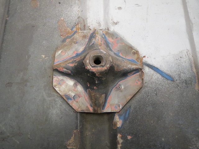
Or, it would have been if the rods went all the way up the chimney. But they jammed about 7-8 feet down from the pot. And looking into it (something I really should have done first) revealed what looked like a plate of some sort. As it was so far down, we couldn't figure out what it was, or why it was there. It felt solid enough that we thought it was a plate with some loose debris on top of it.


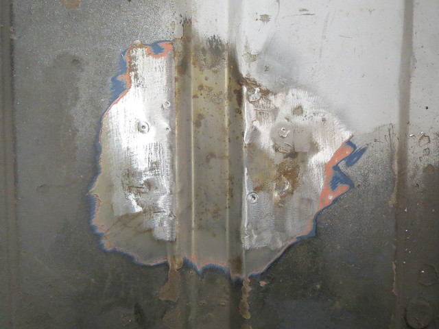
As we thought it was solid, the only option was to remove it from the stack. And the only real way of doing that is to take some bricks out. Which revealed something different what we had expected. Due to being left open, the chimney had acquired a bird's nest at some point, which had then fallen in and jammed at the first bend. There was a total of 18" solid of old bird's nest, sticks and what not in there!


So now we knew the chimney was clear and we could get a pull rope all the way back down to the fireplace. My mate had also stopped panicking at this point. One thing making this all a little easier was the external soot door that his house has. This means less climbing all the way down the scaffold, into the house and back up again as we can just shout at each other through the hole. It will also mean that there's no need to work inside a tight chimney from below as the final joints can be done through the door.

Part of the difficulty in fitting a liner is dealing with 12 metres of coiled up tube whilst so far off the floor. It's too long to do by yourself and too heavy to sling around easily. But that's what mate's girlfriends are for! This is also further proof that there is nothing you can't do with enough insulation tape.


I wasn't able to take photos for a little while after this point as I was sat between the chimney pots shoving the liner in. But the next point was fitting the cowl to the liner and then the cowl to the pot. Whilst there was no need to fit a second cowl, the other chimney had slugs in it from where it has damp, so something to keep the worst of the rain and the birds out was a sensible idea whilst we had access. The second chimney will also be swept soon as well.


And that was it for working outside. We then moved into the house and started knocking the fireplace apart:


And that's the limit of progress for now, as the happy couple are off on holiday! We're not sure what's been done to the fireplace in the past, but there's clearly an additional set of bricks on the left, but without them the arch wouldn't be supported. Which makes little or no sense. Either way, the plan is to remove the new bricks and fit a lintel before doing much else. I'll report back when I'm next allowed near his house with a hammer. Assuming his girlfriend hasn't knocked it down first. She's an architect and a nutter with a hammer in hand.

Friday 17 October 2014

A new approach to the support

Following my frustration at not being able to make the piece of 1.5" tubing fit between the cross brace and the chassis mount, I spent quite a while doing a Google image search for ideas or options I hadn't thought of. And one thing I had thought of but had discounted soon became apparent. I had thought of using a vertical section of tube to mount the short piece of tube to, but I didn't much like this idea. The option I had discounted involved using a vertical strip to run round the mounting plate and to then weld the tube to that. This seemed like a more versatile idea, one that be easier to make and look like better once done.

So I set about marking the plates for where I thought it best to put the strip and therefore the loads. This gave the best compromise between leading straight off the short section of tube and allowing room to fit the captive nuts later on.

Image

It was then on with cutting a 3mm strip overlength so I could trim it back and not risk screwing up the bends. Once I was happy with the shape, it was welded on. The sides were then cut with a slight taper and the sharp corners rounded off too.

Image

Image

Image

With the chassis plate now in place, I managed to find an off cut of tube with just about the right shaped cut on it. This was fitted properly and then a copy was made before I tacked the right hand piece in place. Once tacked, it was removed for welding on the bench. If I were to make this again, I'd probably weld the tubes together and then fit the feet as I can't quite fully weld the left hand side of the joining section. Given the large weld area it won't matter, but it annoys me a little bit that it's not complete.

Image

Image

Once I have the other end welded on, I will cut the excess tube off and probably cap the ends as I saved the cut outs from when I cut the feet brackets. Once I get the tube complete I can then finally get rear wheels on. I had planned on doing this earlier in the week, but everything seems to have taken so much longer than expected. Hell, even helping a mate fit a flue liner on Wednesday involved pulling bricks out the top of the chimney 3 floors up!

Thursday 16 October 2014

Wednesday's update, but a frustrating day

Nothing to update from today, but there is an update of sorts for Wednesday.

The aim for Wednesday was to sort out the Watt's link support in the boot. The first thing to do was to remove the spare wheel support. Thankfully, this is just twelve spot welds to drill out.


And that now gave room for me to start planning out how to actually fit the mount and what it should look like. I figured there were two main options: weld in a brace bar or sort a bolt in version. Weld in is stronger, but removes the ability to easily repair it in the future and it would be harder to fit. A bolt in version would be replaceable but possibly much harder to make. I went for bolt in in the end as it gave me the ability to mess it up and re-do it if need be.

The first thing to do was to cut a pair of plates to fit to both of the rear spring hangers. These would be the mounting points for the brace. Although the photo shows the bolts pointing down, the final version will have captive nuts on the plates to reduce the amount of metal sticking out into the wheel arch.


Then it was on with the cross bar and the mounting feet for the Watt's brackets that hang under the car. These needed to be a good close fit to the 1.5" brace tube, but also be wide enough to provide a wide mounting plate. This is what the final design looks like.


Four of these were then cut out in steel and drilled.


Using the existing mounting holes as a guide, these were then trial fitted to the shell before being tacked in place. The brace was then fully welded on the bench to ensure all four brackets were flat and straight.


Some of the mounting holes that I drilled before will need welding up and re-drilling now that I have a straight set of mounting points to aim for. But this won't take too long to do. The bit that did take quite a while, and even then I binned my last attempt, was to figure out a sensible way to join the cross brace to the spring hanger plate. What I was trying to do was to see if I could shape a short bit of the 1.5" tube to both meet the cross brace and still provide a good wide weld footprint on the plate.

After a good while of trying to get the two to meet I gave up. I just couldn't find a way make the shallow angle between the short tube and the plate work out. I think I will end up having to either use another short vertical section of tube to make the angle flat, which will look like the cups I have been using, or I will need to use two bits of maybe 1" tube to make a triangle between the plate, the end of the tube and the mounting feet. I have some 25mm x 3mm wall tube that would do well for this. I'm not sure which of the two options will be best. More thought will be required before I do either option.

Tuesday 14 October 2014

New A frame completed and ponderings on what's next

Today was a day of mixed achievements. I got less done than I had hoped in the garage, but my son does now have a cardboard box plane that he's spent the day driving Mum insane with!

Today was all about finishing the A frame off and making sure there were no clearance problems. The first parts to make were the two long arms. Making the first arm was a bit fiddly, but it needed to be right as it was also the pattern for the second side. But both were shaped and then welded in before being re-fitted to the shell:

Image

Image

Using such long links on their own isn't the best idea. But that's partly why they're made of a high tensile grade of CDS, which is itself a high tensile grade of steel tube. And also why I need to put the last link in place to complete the A frame. This was made from 3/4" CDS, the same grade that the original A frame was made from. The main links are 1" tubing to help keep things straight. The cross tube was tacked in place on the car before removing the frame again. The frame can't be safely welded with the rod ends in place, as they have a self-lubricating liner, which will melt with the heat.

Image

The frame was then put back on the shell to check for clearance issues. The cross tube was fairly close to the shell, and I suspected I'd need to make a small adjustment or two. It was two in the end as well, one pair of cuts to make the cross tube clear the shell and then I've marked the diff casing as that needs another small cut made to one fin.

Image

With the shell cut back I decided to cut the new drum brake drive shafts down so I could bolt the hubs in place. This isn't needed yet, but I was running out of time so wanted something fairly quick to do before play time was over.

Image

And with the hubs on, the back end is starting to look complete. And it very nearly is. There's just one bit left to make, and that's the link I need for the rear Watt's link mounts. Currently they are just bolted through the floor, which is obviously inadequate. So the plan is to make a cross bar that will link the rear chassis rails together and give a good strong mount for the Watt's links. I may also tie it into the roll cage if I go the whole hog with a 6 point cage. If not, I'll probably link it to the coil over towers. The plan in my head at the moment is to have one straight tube that goes across the centre of the 4 bolts with triangular plates that the go down and out to meet the bolts. A bit of 1.5" CDS should be more than up to the task. I will also probably add spreader plates to both ends of the tube to help both spread the load and make fitting them to the cured chassis rail easier. This will also mean removing the wheel mount, not that I would have used it anyway!


Monday 13 October 2014

Today's progress

Since I'm dying of manflu, or possibly something even more deadly, I was only out in the garage this afternoon. But I did manage to make some progress beyond tidying up.

And that progress is on the new A frame for the rear suspension. As I'm changing the front mounts to be a much stiffer and more secure mount, I need to make a new longer A frame to match. The new mounts are based on the existing mounts, but cut down. The idea is to move the mounting brackets so they are in the middle of the bolts, rather than hanging off the shell on the bracket. These are the existing mounts:


And this is what they look like when cut down to the size I want:


The new brackets are based on a template taken from the existing mounts. All four were roughly cut but accurately drilled before being bolted together for shaping. This ensures all four are the same shape and have the mounting hole in the same place.


The brackets were then roughly assembled with the rod ends, threaded inserts and spacing washers, to allow a little extra adjustment should it be needed, before being tacked into place:


So with the brackets done for now, the threaded inserts needed welding into short sections of CDS. I decided to use these rather than rubber bushings as they're easier to make for a DIYer. Bushings require accurately sized tubing and are often press fit, and I don't have a press. And rod ends also allow a degree of adjustment that bushings just don't have. Plus, they're shiny.


These were then bolted back into the brackets and the whole lot put back on the shell.


With those done for now, the De-Dion tube mount needed remaking too. The Caterham A frame uses 1 1/4" tubing, but I didn't have any so mine are 1 1/2" instead. The only difference this made was that they needed a slight angle filing on one edge to clear the welds on the main tube.

Building up to another week off

Since I have some holiday stored up, I'm taking this week off work to make more progress on the Sprite.

In preparation of having the time off, I wanted to get the Mini uprights cleaned up and in primer. I need to get the outer suspension components together so that I can set the wheels correctly in relation to the shell before moving onto making a trial set of wishbones. The easiest way I know of cleaning up old rusty parts is using the power of science.

Since they were free, they used to look a little worse for wear, like this:


But if you put them in a bucket of water mixed with soda crystals and add a battery charger you can use the electricity to reduce the rust on the surface back to iron. This process takes about half a day for each part in my little plastic tub, but that's about all. It's cheap, a piece of piss to do and makes very little mess. It also leaves any machined surfaces perfectly intact and can remove a fair bit of grease too. This was my initial set up, and they were left in overnight:


Once taken out, they look better. Not great, but better. Ideally, you should surround each part with anodes (the scrap bits of steel), but I only had two usable bits to hand.


Since they weren't great, I decided to put them back in individually to get them looking better. Once they're given a quick wire brushing to remove any flakes of rust/iron, they look like this:


Not bad for 10-15 minutes work. OK, a blast cleaner would probably do just as well, if not better, but I don't have one of those where as I do have a battery charger and a bucket. This process can be applied to any iron/steel item and the only real limit is the size of the tub and the charger.


IMPORTANT 'Ealth and Safety bit: should you fancy having a go at home, please do. But DO NOT use stainless for the anodes. It makes a rather nasty chemical in the water called [url=http://en.wikipedia.org/wiki/Hexavalent_chromium]hexavalent chromium[/url]. It's mildly carcinogenic and can cause contact dermatitis. Make sure you put the negative wire on the thing to be de-rusted, as getting it wrong makes the part more rusty! Where possible ensure it's done in a ventilated space as the process gives off hydrogen gas in small volumes.


Once they were both clean and dried off, a few coats of engine primer were applied. I'm using that over other stuff as it's supposed to resist temps up to 500F, which should be way above what the uprights see. At some point I'll probably paint them black but they'll only get knocked in the next few weeks, so I don't see the point yet.

Saturday 4 October 2014

Record 74 painting

As part of tidying things up a bit of late, I decided it was probably about time that I actually got at least one of the Record 74 Autovices I have back in one piece.

So the one that was in bits has been treated to it's few two coats of Insignia Red enamel. I've no idea if this is the right colour, and chances are it's not, but it's a good match if maybe a bit bright.


The colour in real life is somewhere between the two photos, with it being nearer the red of the second photo. Once this coat has dried, they'll get a third and final coat before I contemplate putting them in the oven when my other half isn't looking to really harden the enamel! I might just have to leave in a box for a few weeks instead though.