Once again, I've forgotten all about updating this blog!
Much has happened in the past month, and I'm please with the progress.
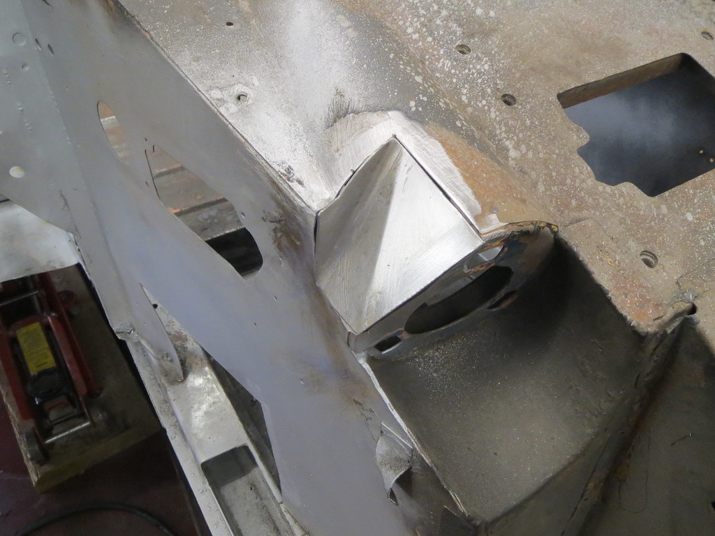
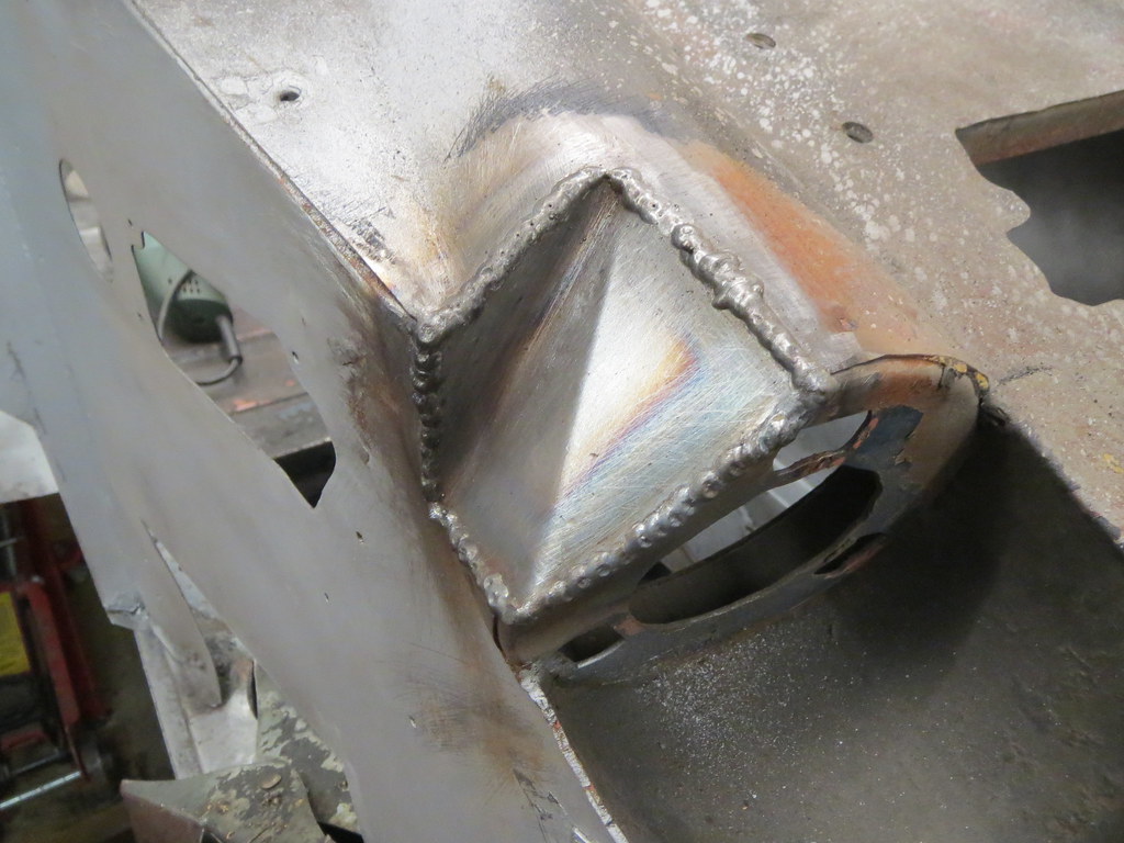
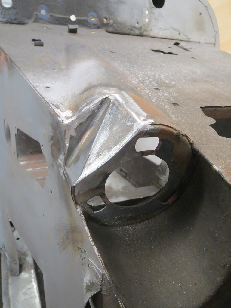
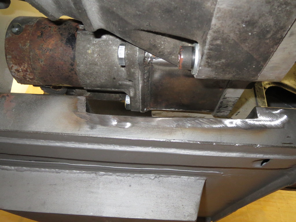
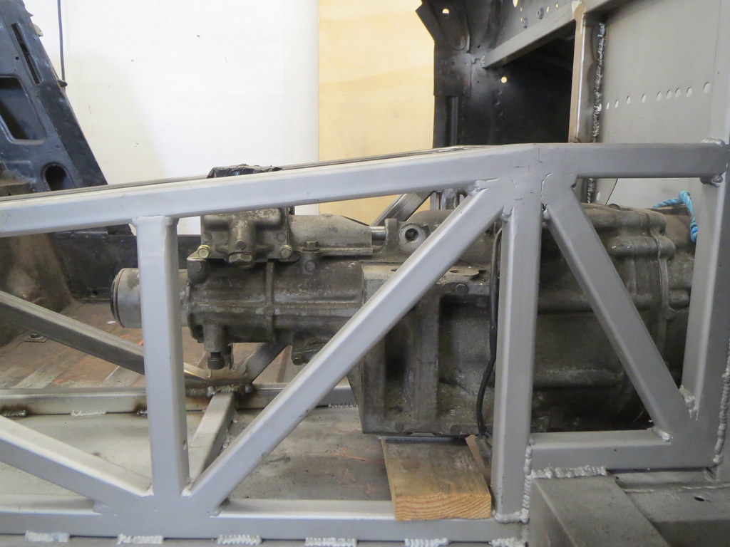
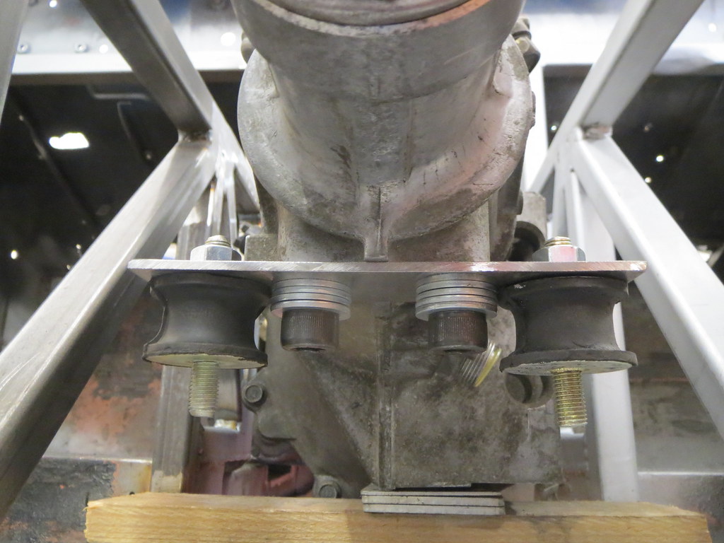
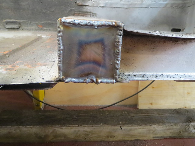
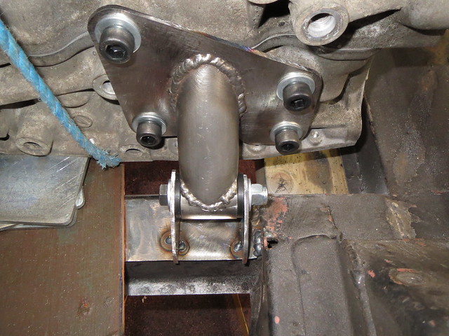
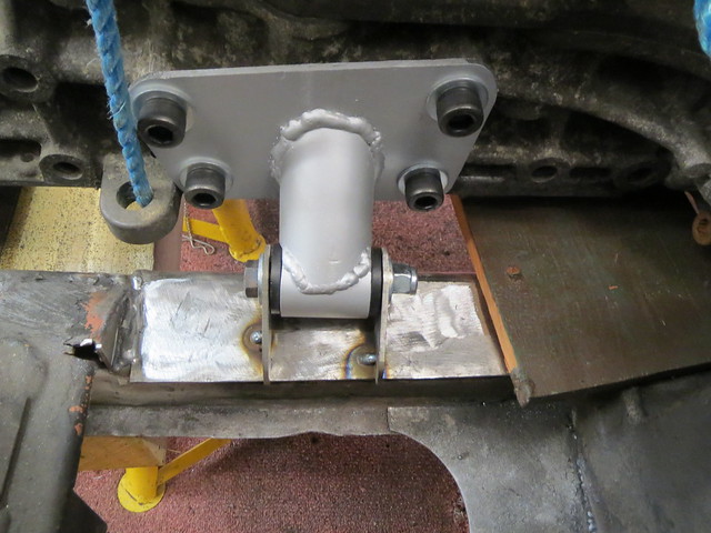
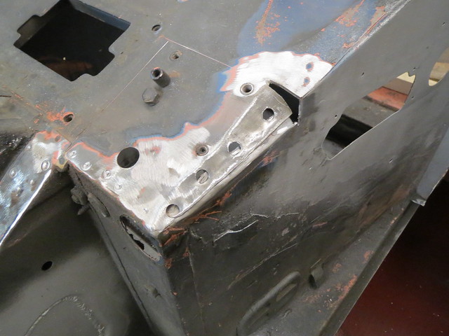
The gearbox mount was completed, but found to have a bit too much vertical deflection in the flat plate across the gearbox. So a simple fix was to replace it with a shaped piece instead.
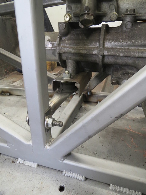
There is now less than 2mm vertical movement with my 100Kgs stood on the tail of the box!
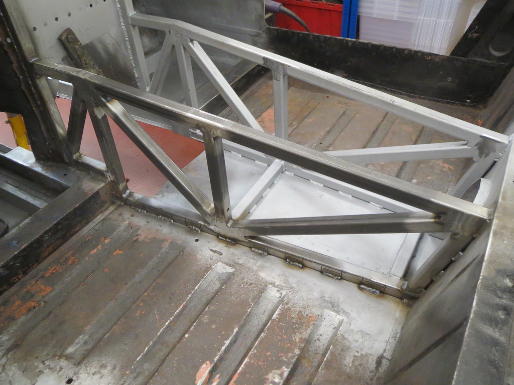
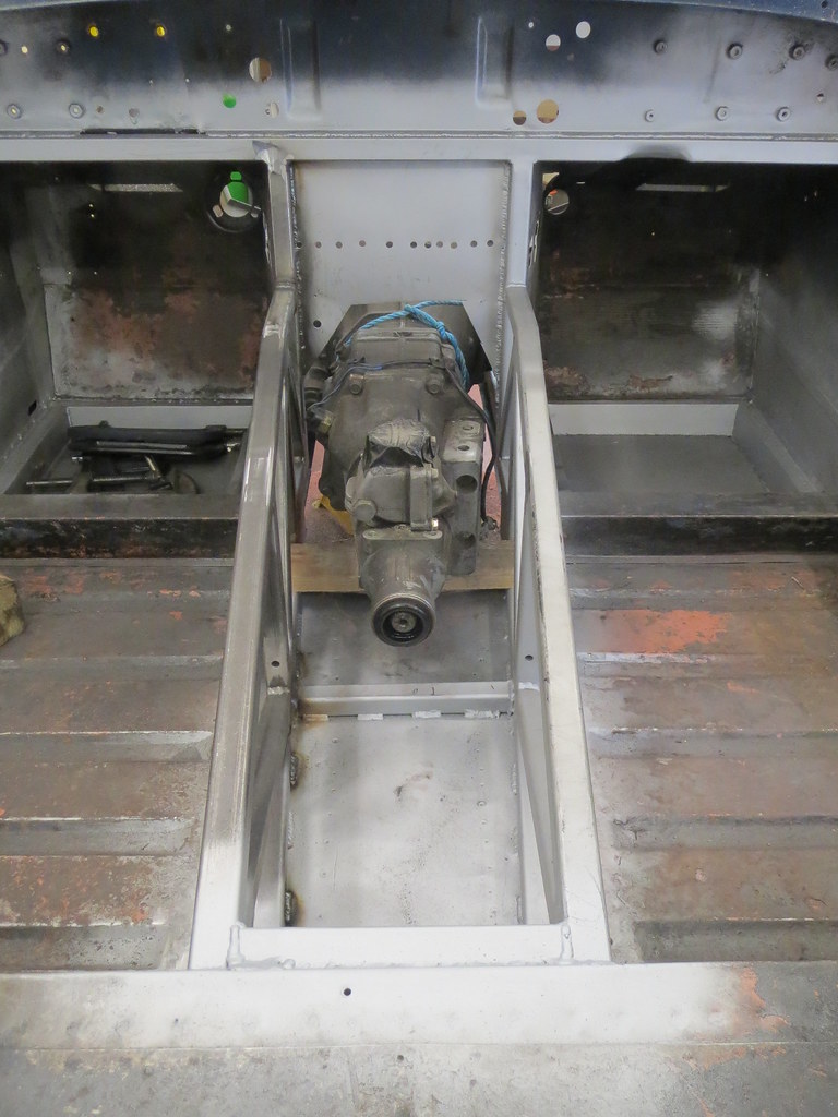
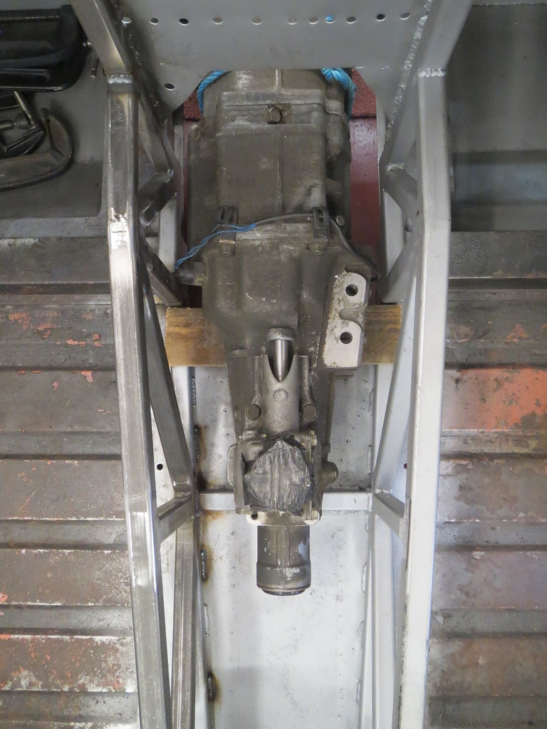
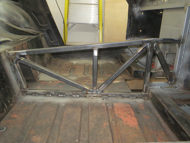
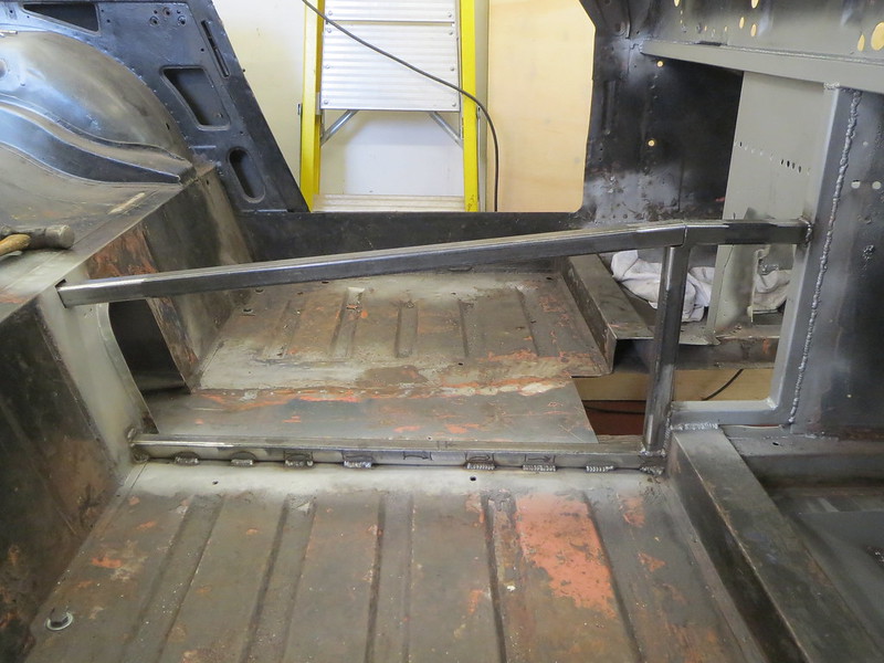
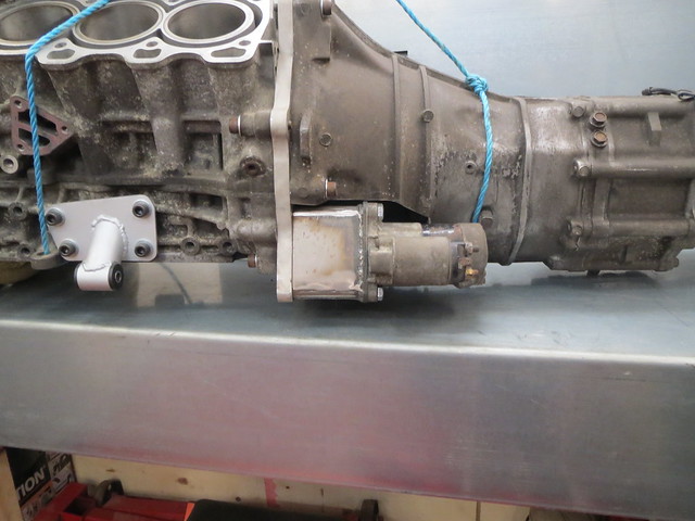
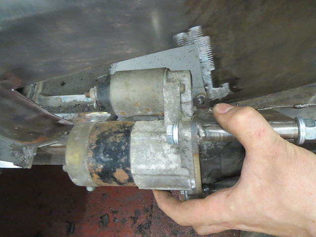
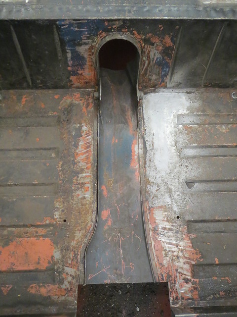
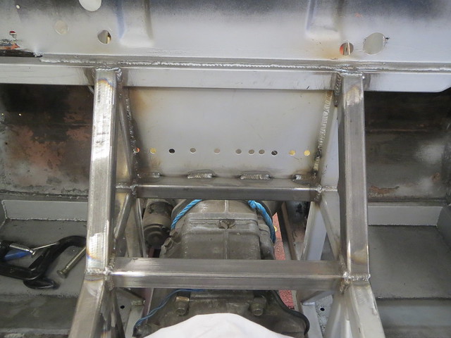
With the engine and box now fully mounted, more work on the tunnel was done.
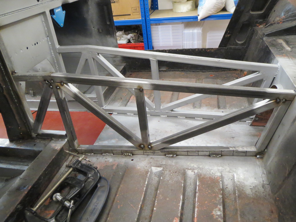
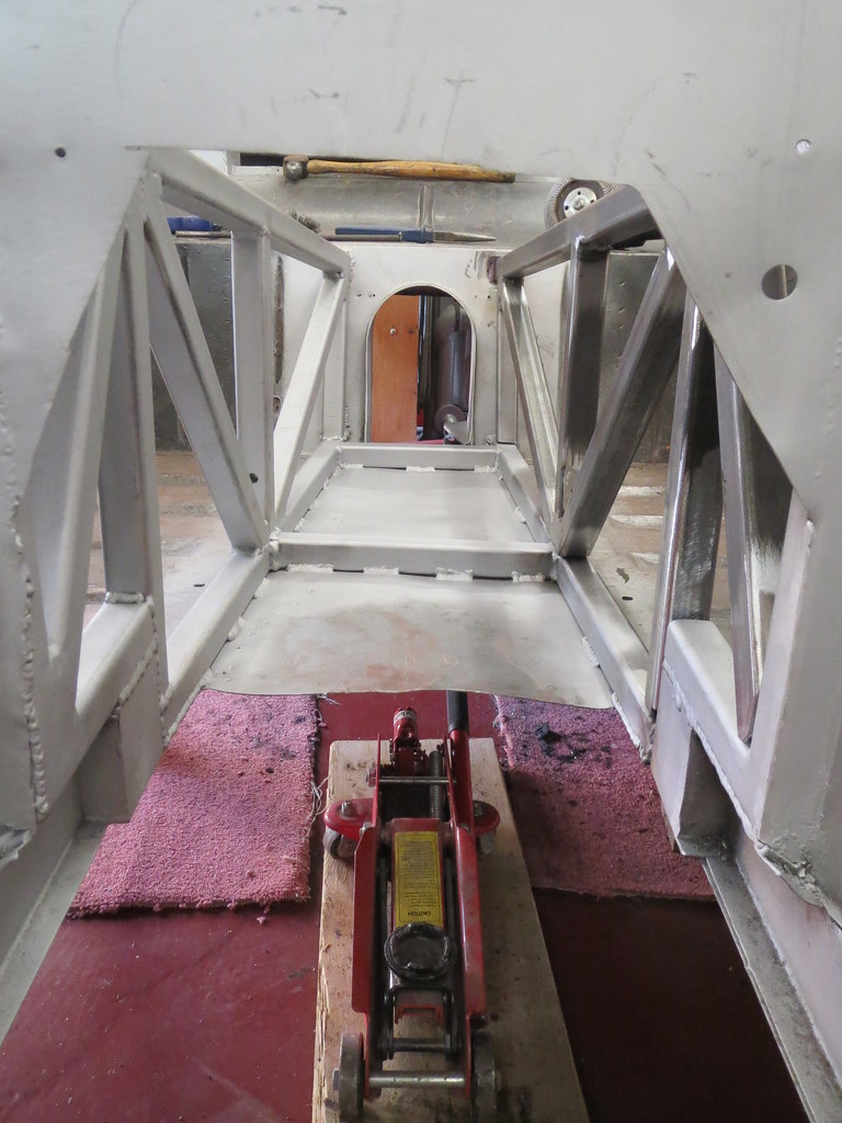
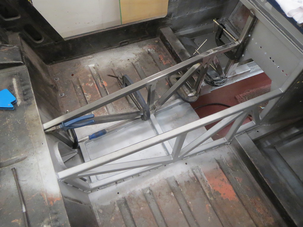
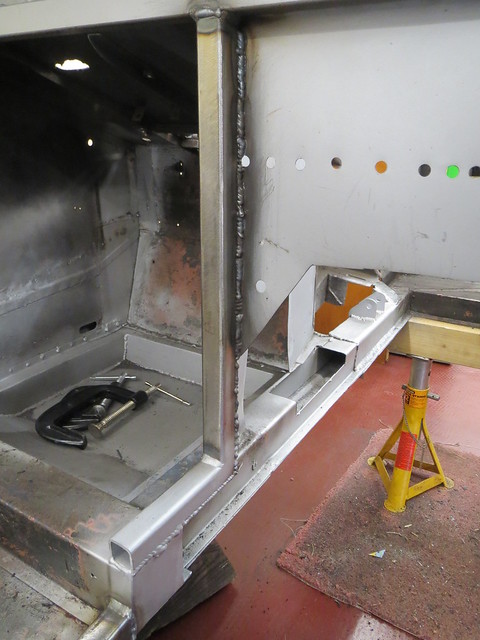
First the cross tubes were fitted:
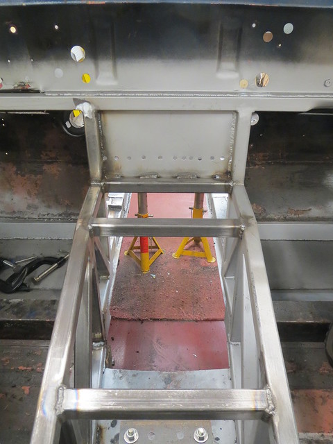
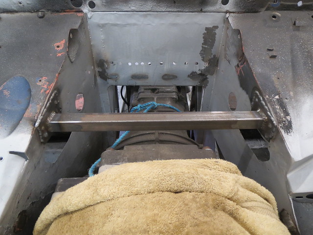
And then diagonals from the frame up to the dash tube:
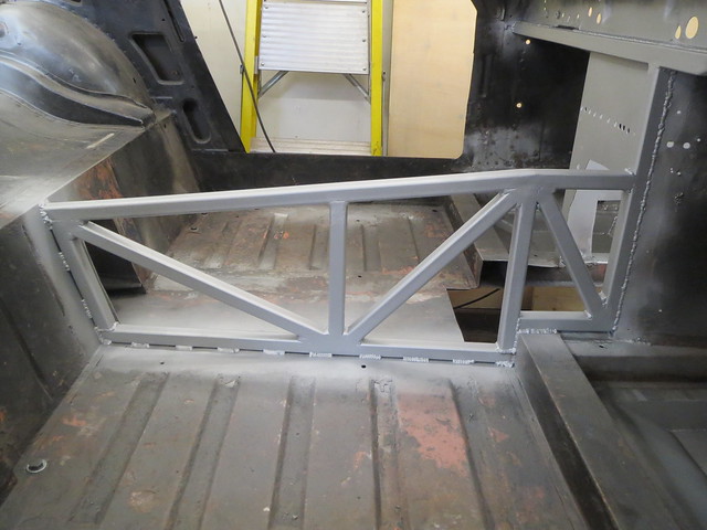
For now, that's the tunnel completed! I still want to add diagonals that go from the front bulkhead up to the dash tube, but I need to have the dash and steering column fully mounted before I go ahead and do those in case of clashes.
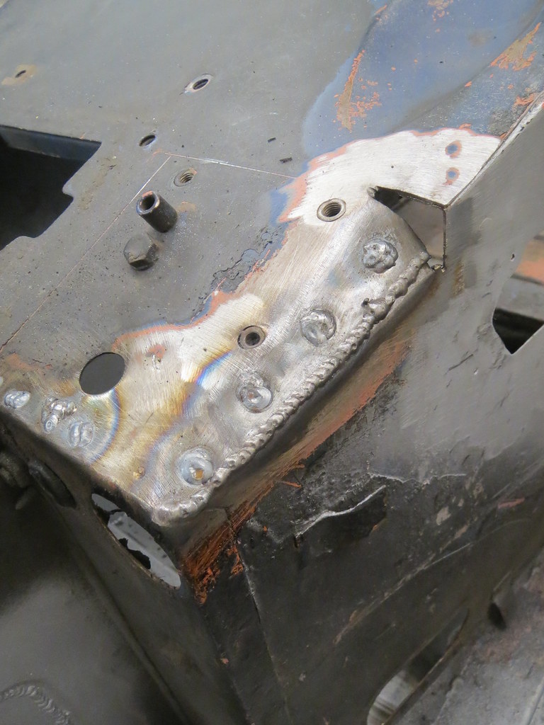
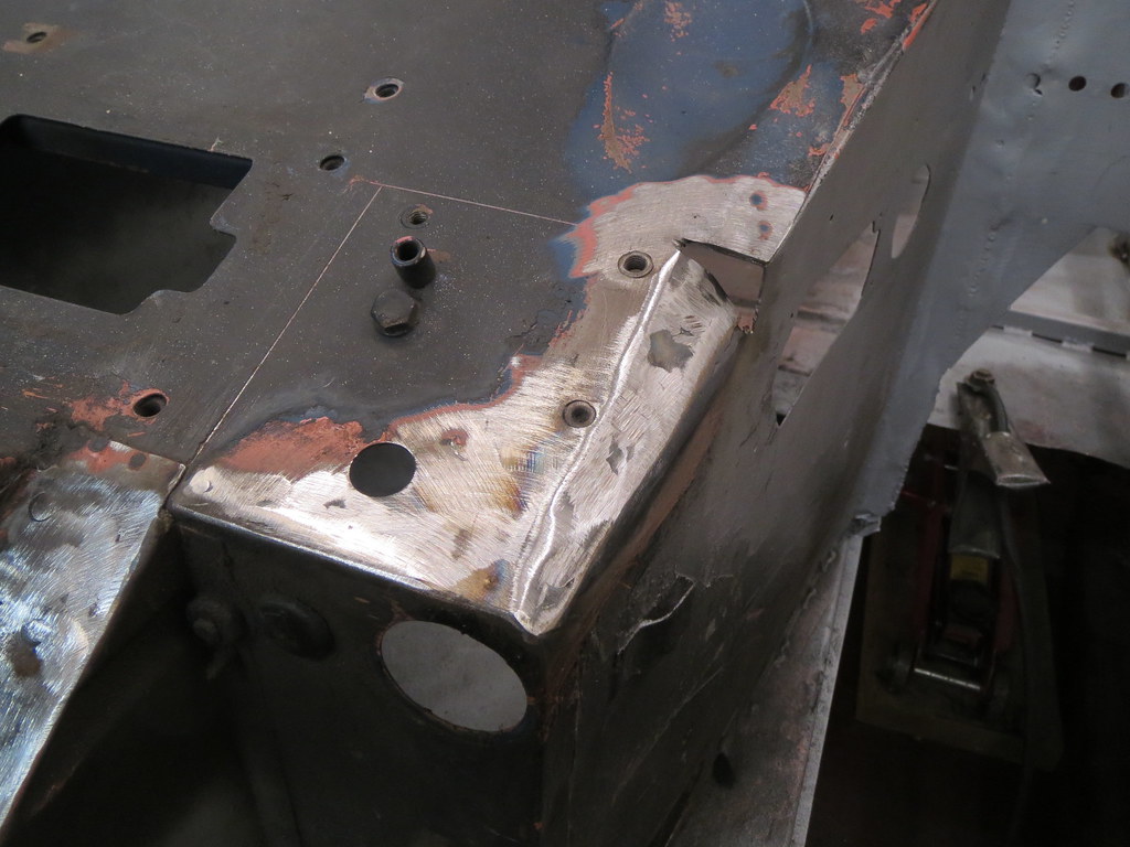
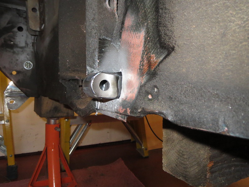
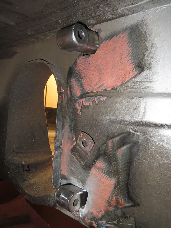
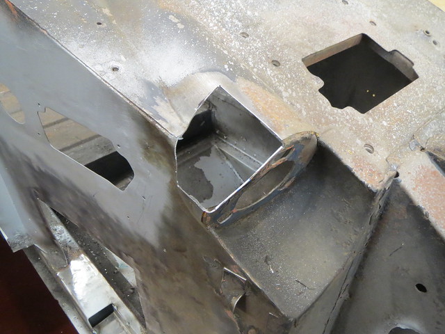
The next thing on my list was to do some more work on the rear suspension, specifically mounting the coil overs at last. The first step was to make the top mounts. This are just simple pieces of 3mm angle, with a section of M10 threaded bar welded into place. One side is longer than the other to aid with locating, as the coil over needs sliding up into the tower from below with one hand, whilst trying to get a nut on with the other hand inside the car. With one peg longer, they can be located one at a time. As clearance is tight, I also need some shorter bolts.
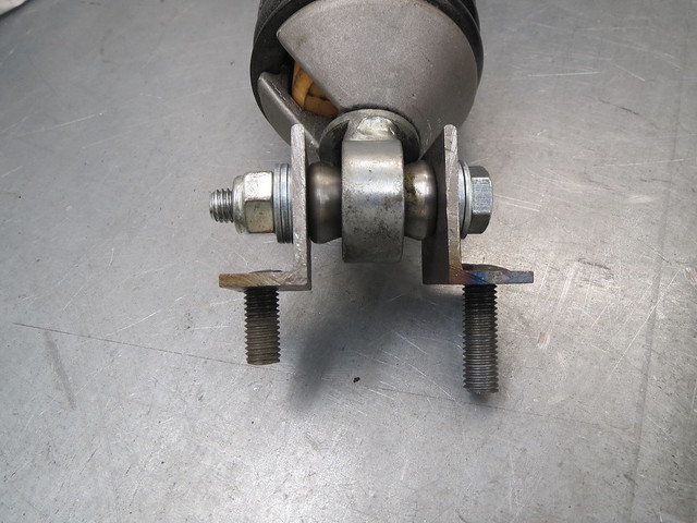
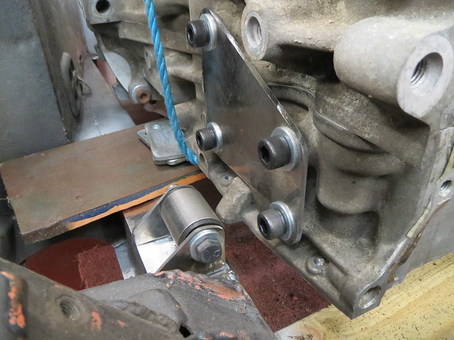
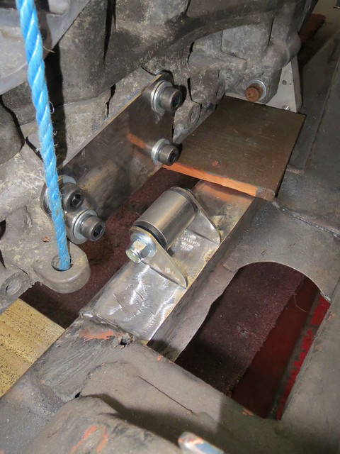
One problem with the coil overs I have is that they have cone shaped washers, with a 10mm hole as that's what Caterham use on the CSR. However, the De-Dion tube is designed to take a 1/2" bolt, so the washers have to come out, but that leaves a 15mm hole! I'll need to sort something out for this later on, but for now I've just made up a spacer using a 1/2" nut so I can check everything fits.
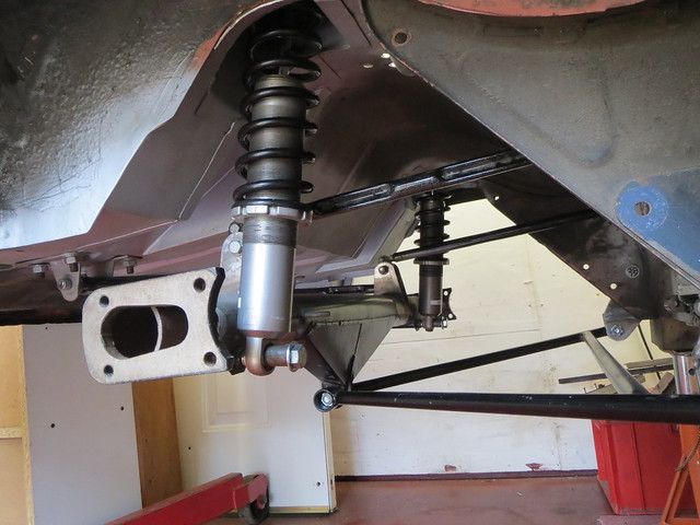
With both sides done, the rear linkages are all now hanging under their own weight for the first time! Once I get hold of a set of the end brackets or ears, I can make a start on hanging the hubs and so on before getting the diff spider made and fitted.
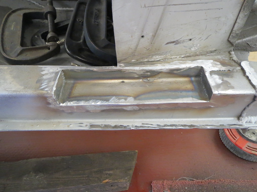
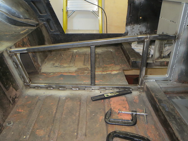
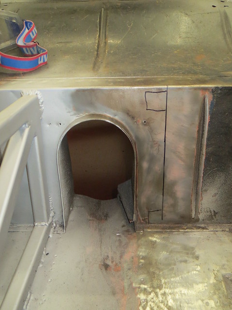
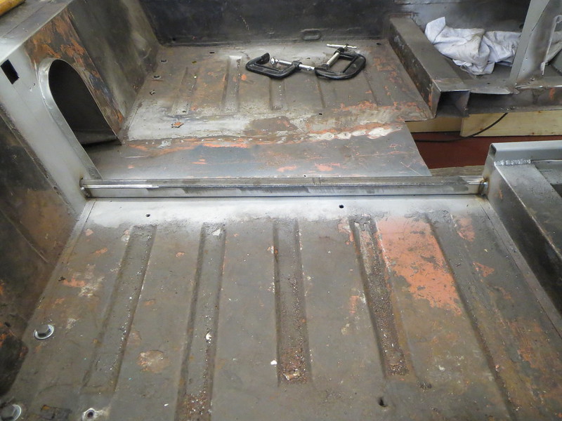
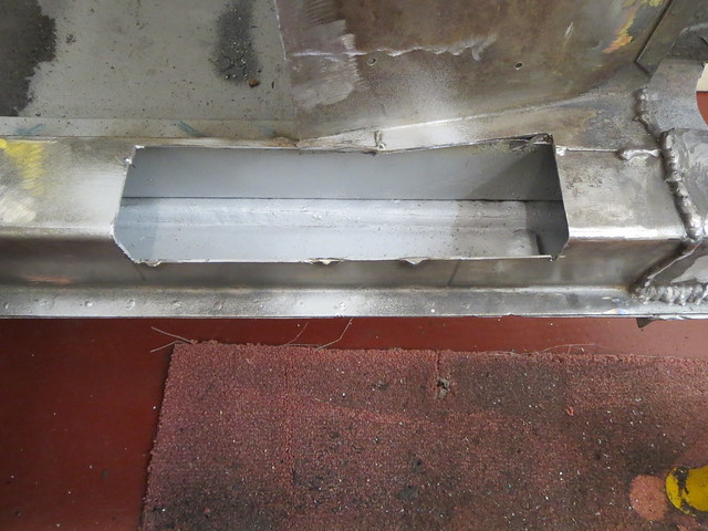
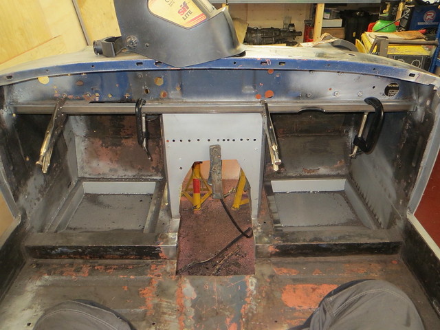
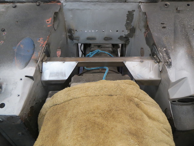
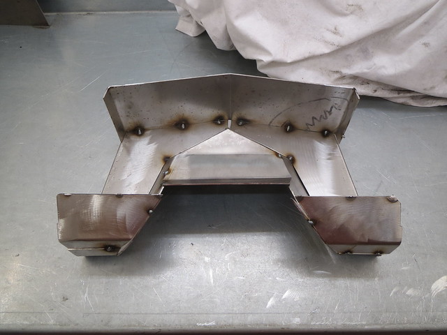
Since I was feeling all good and optimistic, I decided it was a good time to tackle the heater tray. The original was cut out ages back to allow the engine and box to fit. And now they're mounted I can make a replacement for it. It was also a chance to create a little extra rigidity in the foot wells.
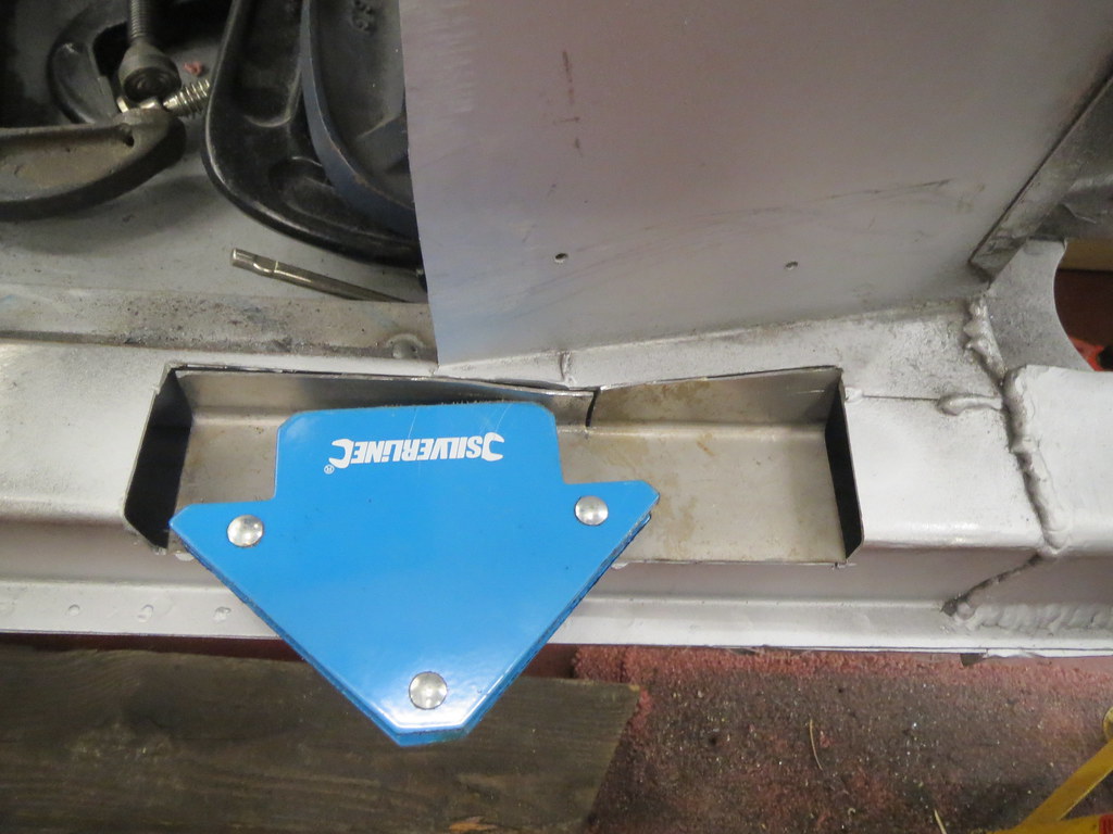
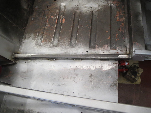
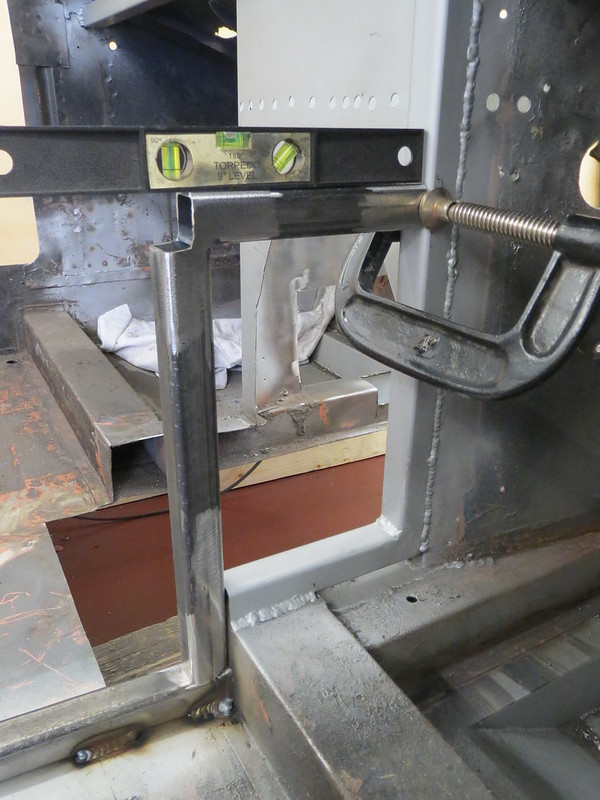
The first thing to do was to fit a length of 1" box between the footwell panels. It had 16 SWG plates added to each end to spread the load.
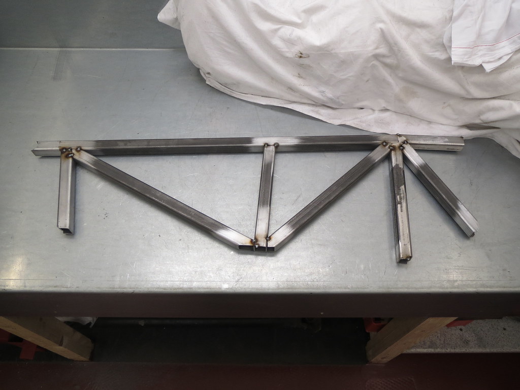
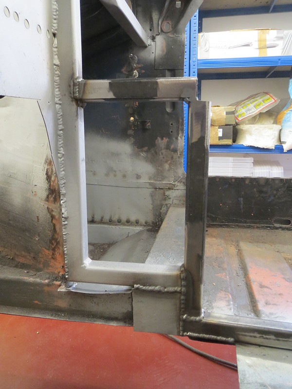
This then gave a fixed point to work off for the leading edge of the tray. The plan was to make each section as a card template, before reversing that template for the other side, like this:
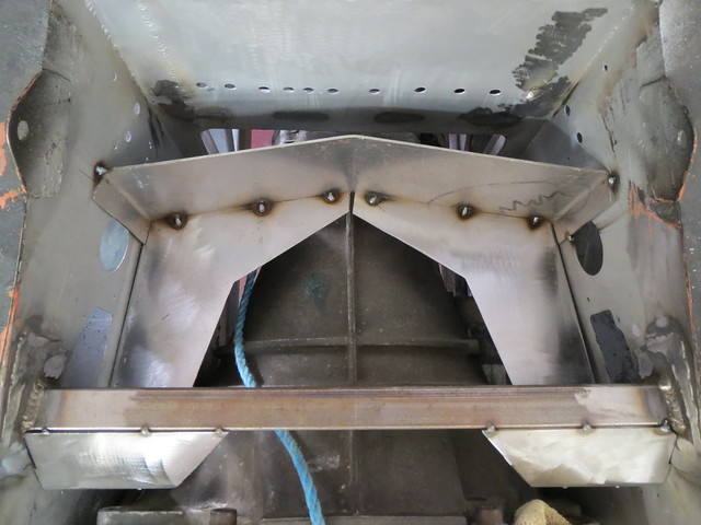
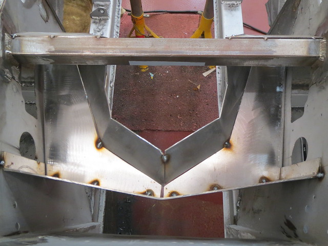
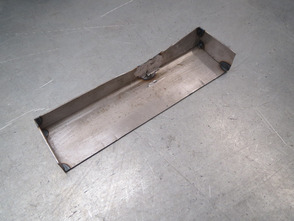
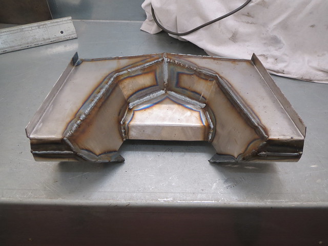
With the whole thing tacked together, it could then be removed from the shell as one piece and welded up on the bench:
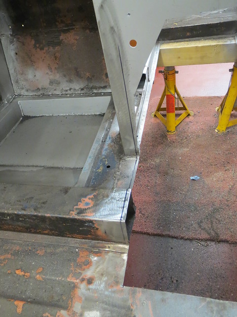
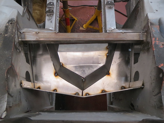
Once cleaned up, the whole thing was given a coat of primer and left to dry.
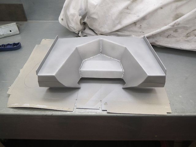
And that's pretty much where I am now. The tray is about to go back into the shell, but I've got the spot weld holes to drill first.
On another note, I'm still trying to find a set of seats that will sensibly fit into the space I have for them. For a seat roughly 600mm long, the front can only be 460mm wide. This is smaller than the vast majority of seats so finding something second hand may be hard work. I might even have to resort to buying something new!! Or just use GRP shells for now as I imagine I'll only be carry adults whilst I get the car reliable. I'm not sure which will work out better in the long run. Not that there's any rush to decide, mind you!
Following on from a few projects that have been scattered to the winds on various websites, I thought it might be about time I put all the various bits and bobs I do in one place. Welcome the The Workshop.
Search This Blog
Wednesday, 30 July 2014
Sunday, 29 June 2014
Yay, engine and box back in at last!
So a few more weeks have gone past, my best mate is now married to his beautiful bride and I can get back to work on the Sprite!
From where I left off with the frame, I got the second side cut and tacked into place. I then decided to cut the entire side out and weld it on the bench. This means I can do all the welding the right way up, but it does mean a bigger hole in the bulkhead so I can fit the diff mount end of the frame in.
Before it was welded in, I fitted two of the lower frame tubes before access became awkward round the frame. The rear most tube should be hard up against the bulkhead, but I decided that the work needed to do this wasn't worth the effort. So the tube sits roughly 1" forward of where it should be.
The only bit of the frame I could safely fit for now was the rear top tube, against the bulkhead. The welding needs tidying up as yet, as I had the bulkhead hole to fill in slightly.
The rest of the frame tubes had to wait until the engine and box went in, as I knew some may sit in the same place as the box. However, before I could fit the engine and box, I needed to close off the footwell tops and the chassis rail notch.
I've left the small infill piece out of the RHS footwell for now as it might come in handy for running cables for the ECU, since it's so close to the engine.
The chassis notch took a bit more time to do, as I had to form an odd shaped box:
And so I could get the engine and box back out from under my bench and into the shell. Thankfully, there's loads of room round the gearbox. I haven't checked the heads yet, as that can wait for a quiet evening to do.
It's just as well that I decided not to fit the other cross tubes, as the next one forward would only just miss the gear turret. The other would fit above the box though. I also have space to partly replace the chassis cross member with a lower version, which is good news.
The next thing to do was the gearbox mount. This is a Mk1 go at it, as I'm not sure if this is the best way or not yet. I'd like to be able to screw the bobbins straight to the box, but I can't find any with an M10 x 1.0mm thread.
The frame bracket is formed from a strip of 2mm sheet bent round an off cut to give a good fit. I ran out of time to start cutting the tube back to suit, so that's the next thing to do before making a matching version for the other side. I may link the two halves together yet to make it stiffer, but I'm not sure. I'll wait until both sides are done and then see if I can move the box about at all.
Wednesday, 4 June 2014
One side down, and work started on the second
With the top rail in place, the two vertical(ish) tubes were cut and fitted. The rear tube was straight forward to do as it just sits against the bulkhead face. The central tube is harder, as it will hold the gearbox mount.
Firstly the tube was fitted to the rest of the frame.
The tube was then drilled to accept a short bit of 12mm bar that would form the crush tube. Once this was welded in, an 8mm hole was drilled through it. The completed tube was then welded into the frame.
So now the main frame was complete, it was on with the diagonal brace bars. These are simple enough to do once the frame is solid, as you can just hold the new tube against the frame and mark off where the cuts need to be. The frame has three diagonals in it.
Fitting these proved to be harder than I had thought, as getting good access to some of the welds was difficult. There was one or two where I could only just see what I was doing. Because of this, I will try to make the other side of the frame off the car so I can turn it round and see what I'm up to next time. But once I'd ground the facing welds flat, that was this side of the frame done! I'm really pleased with how it looks, and I at some point I will need to decide which seats I'll be fitting. Not that I have much choice, as the space is now even more limited than usual!
The other side was the next step, and lots of measuring was needed first. Since I had cut the cross member and floor to be roughly right, I needed to cut it back to be exactly right so it didn't underhang the frame. Thankfully, I was only 5mm out with my original cuts. The rear bulkhead was also marked out.
Once cut back and cleaned up, I could then cap the cross member before making a start on the frame. Once the welds were cleaned back, I had to re-do a tiny bit as I'd missed the edge of the panel slightly.
As with the first side, I started with the front section of the frame to give me something square to go from. I also hammered the floor section under the rail closed and welded that up whilst I was there.
The next tube was the lower rail, but it seems I had twisted the floor slightly when welding the first side of the frame in. I know it wasn't flat to start with, but I think I've made it worse. So I had to stand on the tube when putting the first welds in to keep it square. Since I've been thinking about fitting a floor under the engine bay, I may cut the centre of the floor out yet and replace it with ally sheet.
The only other thing to report is that I am now minus my favourite kneeling pad. It turns out that I really should have looked under the car before responding to my neighbour's call over the fence, as I had managed to set the pad, and then a bit of carpet on fire!
The best bit is that it wasn't even me that spotted it, but my 21 month old son Noah who was busy pointing and shouting at me! If he hadn't seen it, I'm not sure what would have happened. So a lesson learnt there!!
Monday, 19 May 2014
More tunnel work
I'm not doing a brilliant job of keeping this blog up to date, but I am making progress.
Now I had a base for the tunnel frame, I could make a start on the rest of the rails for this side. The bottom rail was trial fitted before having it's closing piece fitted to the rear end. This will close the tube off and also give any diff cradle something to bolt to.
With that in place, the next section along could be made up and welded in place.
The top rail was next. I was in two minds over if I should make this rail from round or square tube. Round would give a nicer edge/curve to the top panel, but square is easier. I also have square tube, and the only round I have is expensive CDS, which I will be using for the wishbones. So square won out in the end.
That's it for now, as that took a while to get right although the top rail is fully welded in the cabin. I can't rush this bit, as once the rails are in, cutting them out will be quite a task. The next steps are the two remaining vertical tubes, and then the cross braces.
Saturday, 10 May 2014
Busy, busy, busy.
I've been rather busy over the past three days!
The engine mounting plates were cut out and the chassis tabs bolted to the bush tubes for trial fitting.
And then the joining tube, 38MM CDS was cut and shaped. Everything was lined up and then welded together.
With the mounts done, and the engine sitting square in the shell, it was time to fit the starter motor to the gearbox. The MX-5 box I'm using doesn't have a space for a starter, so I've had to make one.
With the starter now bolted into place, I could get the engine back in the shell and start lining up for making enough clearance space for the cylinder heads and the starter.
The starter needs a hole in the side panel, and a notch in the chassis rail.
And then both footwell tops were alter to clear the back of each head.
None of these bits have been welded up yet, in case I change my mind at some point about the amount of space I want. I doubt I will, but you never know.
So that was the engine side of things sorted for now, and it was on with the next step: the new transmission tunnel. There were the remains of the old tunnel to remove first so that I could start measuring up for the new design.
The first step was to fit a cross beam to the dash panel
And then I could get on with fitting the other tubes. I didn't get far before I ran out of time, but I now have a solid base from which to work.
Subscribe to:
Comments (Atom)


