Search This Blog

Tuesday, 3 March 2015

Finishing the jig and starting the wishbone

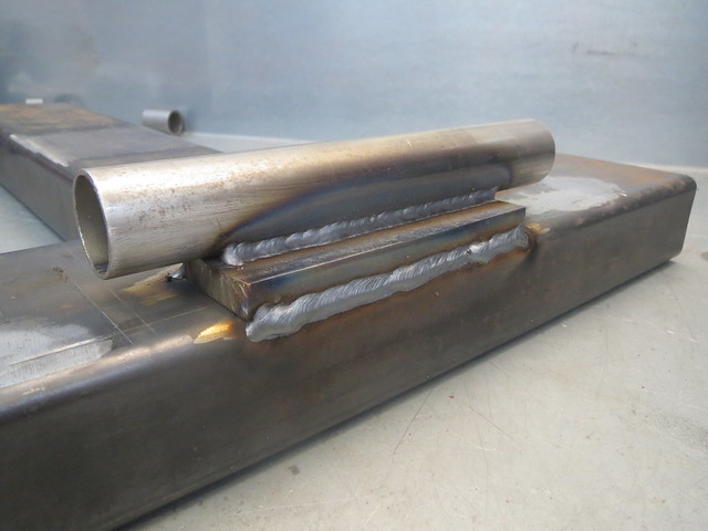
I've been spending some time looking into jig building and how to do things for the best. Ideally, I'd like to make a jig that would allow me to fully weld all the joints in place, but I'm not sure I can make such a jig with enough accuracy, or if it's practical with the ball joint pin I need to add. So I've decided to alter the frame I have to better suit what I need. And that meant cutting off the existing brackets and welding in a support tube so I can clamp the pivot tubes in places. This has the advantage of not needing the nylon bushes to be in place, as the heat of even tack welding would melt them a little. They're also a bugger to remove without trashing them. Whilst I was there, I raised the tube off the frame a little to help with clearances.

Image

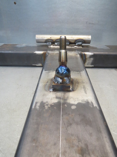
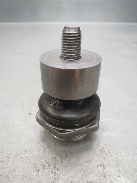
The next thing to do was to double check all the measurements I could and then to line up and weld in the ball joint pin. This too was raised off the frame to maintain the line between the centre of the pivot tubes and the centre of the ball joint ball. These are the points that matter as they're the ones that everything revolves around, regardless of the shape of the rest of the wishbone. The hub measures as having a 18.1 degree angle against the hub face, and I'm quite happy with the 0.1 degree difference! And whilst this might sound a bit geeky, I love the colours on the polished ball!!

Image

Image

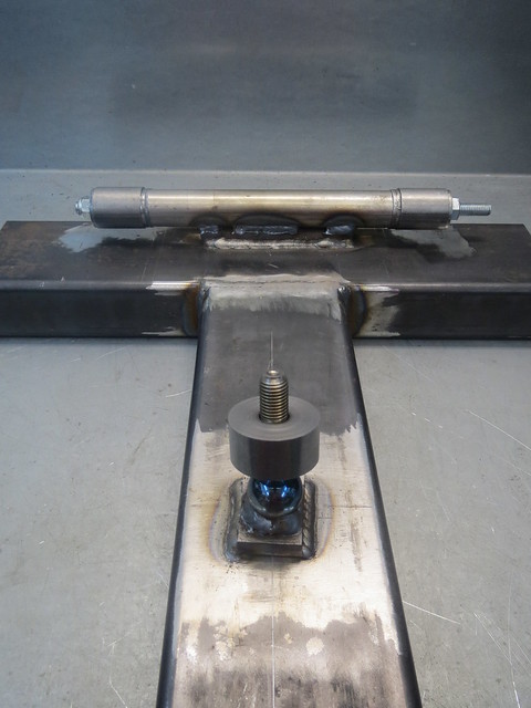
The idea is that the pivot tubes and the ball joint bush are then set in place so I have a template to cut the main tubes for. As the lower wishbone aren't handed, this jog will do for both sides.

Image

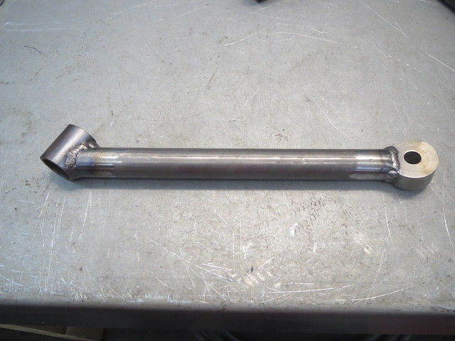
Cutting the tubes to match the pivots is the easy bit, but fitting the other end to the bush I found a bit harder, as the bush doesn't sit square to the wishbone, and needs it's lower edge to be level with the tube so it doesn't block the ball joint. It has to be offset to centre the joint and give the maximum movement without binding. Cutting this one tube took me about an hour! I do expect the second one to go quicker though. I also found that trying to set both pivot tubes and all 6 washers at once is impossible, so I left one side out.

Image

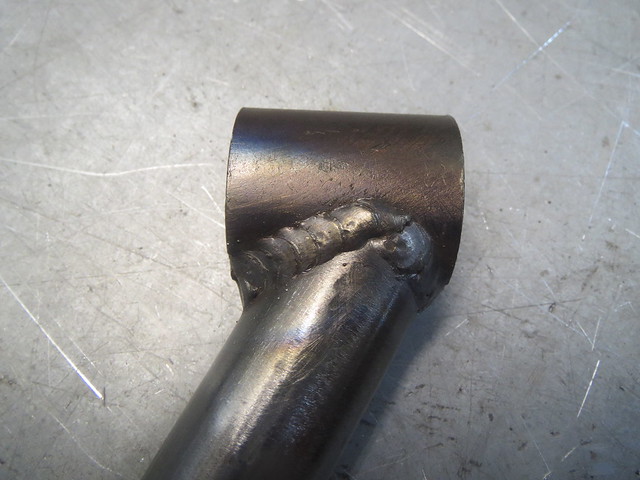
With the tube tacked in place, I decided it was best to remove it from the jig so I could fully weld it. The bush end needs doing at this point anyway, as I can't get at it fully once the other main tube is in place.

Image

Image

Image

Tuesday, 24 February 2015

Bushes machined, new type of hubs arrived!


Got my parts in the post from Red 7 Autoengineering. I had 8 bushes machined so I can cock a complete set up of wishbones up and still have enough left over for another go. £65 for them all, posted, and I'm well pleased with them.

Image

Image

So I can make a start on lining things up for the jig and the first version of the lower wishbone. There will be an inner end bracing tube and an outer end gusset to spread the load and give me somewhere to stick the coil over.

Image

Tuesday, 3 February 2015

The beginnings of a lower wishbone

With a few hours to spare today, I managed to get out and get a little more done in the garage. Most of what I've been doing of late has been research into the front suspension. Things like a direct hub to hub width are hard to find, as they vary with suspension travel. But this is a measurement that I need an idea of to start lining up for my wishbones. I have finally managed to figure out something pretty close to what I need, so I could start setting up at last. And it turns out that the BMC/Austin designers only worked in nice even imperial measurements.


So I now need to make a start on a 10" deep A frame wishbone. The plan is to make a jig to allow me to mock everything up and alter it easily as I discover problems that I haven't foreseen. The basis of the jig I have had lying about for ages, waiting for me to get to this point at long last. It is based on large box section, welded into a T shape. The plan is that I will have the upper wishbone jig on one side, and the lower on the other.


The main issue I face now is that I need to find somewhere to machine me the tapered steel end pieces I need for the outer joint. Without those accurately tack welded in place, I can't make a start the wishbone tubes. These will be the same 1" tubing that the rear A frame is made from as I have loads of it and it's strong as hell.

Thursday, 22 January 2015

Some minor progress after a bit of a lay off

I've just realised it's been two months since I last updated this thread, but that's mainly because I've been too busy to devote any real time to the Sprite. I have managed to get a little more done, but not a lot.

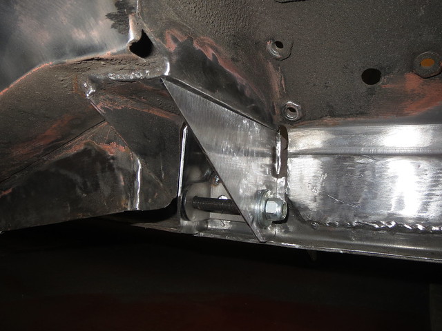
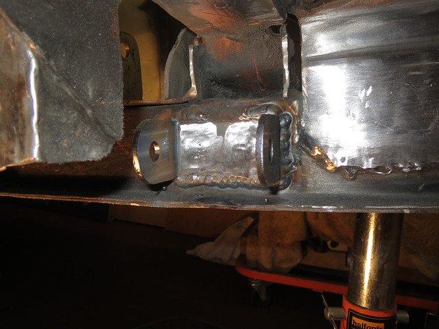
I was planning on getting the rear mount tidied up and painted, but I wanted to make a little more visible progress so I set to with the front mount. Having made the templates previously, this was mainly a job of transferring them to 2mm sheet. Due to the way I'm making these mounts, the first section is the one designed to feed the loads into the chassis rail. The other sections are there to both support the first one, as well as brace the suspension tower and the rails to each other. The first job was to weld the front mount itself in place:

Image

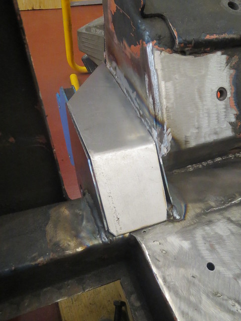
This then lets me make the final adjustments to the steel sheet sections, one of which needed a small section welding to the back to close off the gap to the suspension tower.

Image

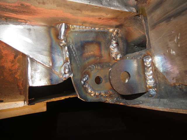
These two bits were welded in so I could make sure the top section fitted. Whilst I could have re-made it to close the gap on the right hand side down a little, I didn't think it worth the bother.

Image

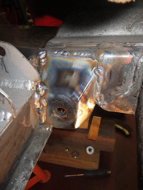
As before, all the sections are seam welded on both sides.

Image

Image

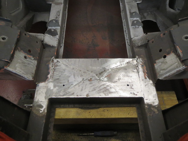
I do still have the weld on the rear support to the chassis rail underneath the suspension tower to do to finish this mount off. But I was getting a crampy back from being curled up on the floor, so I left that weld for another day. To give me something else to do, I decided to cut the coil spring mount out. There was just too much rust showing so it had to come out. Just a shame it took me hours to do, as it's held in with a good few spot welds as well as some little seam welds which I couldn't get to to cut out with the grinder so it was a tedious process.

Image

I am now seriously contemplating some form of brace to go in the box, as that tower will be taking the loads from both the coil over and the top suspension arm, so it can not flex. As it is, the box is just too big/too open for my liking. I my just put the cover plate back a little inside the tower and then brace forwards as it'll be easier to fabricate than trying to make a frame to go behind a cover plate.

Monday, 24 November 2014

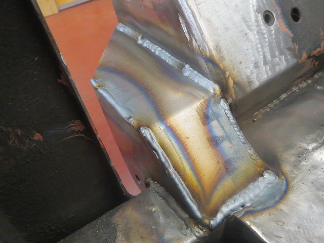
Rear mount done.

I managed to get a bit more done on Saturday. I decided to leave the tower cover plate for now, as it would block access to the reinforcing webs that I need to replace.

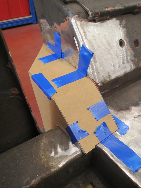
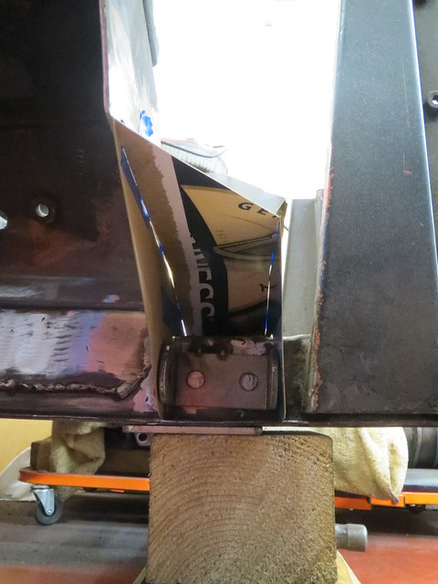
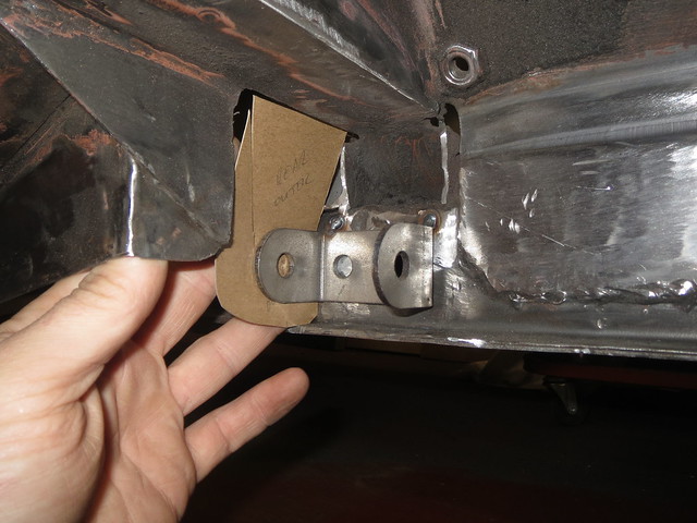
Whilst I waited for the garage to warm up a bit, I had a bash at the templates for the front reinforcing plates. The idea is to have them vaguely replicate the original ones, only a bit wider to suit my brackets. I may change the plan a little, but I can't think of another sensible way to make this.

Image

Image

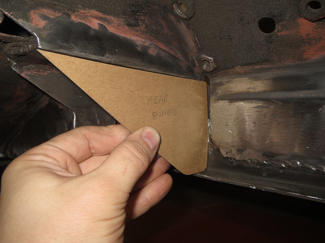
Then I moved on to the rear reinforcing plates. One would be a simple flat plate, but the rear one would be more complicated to fit and weld in.

Image

Image

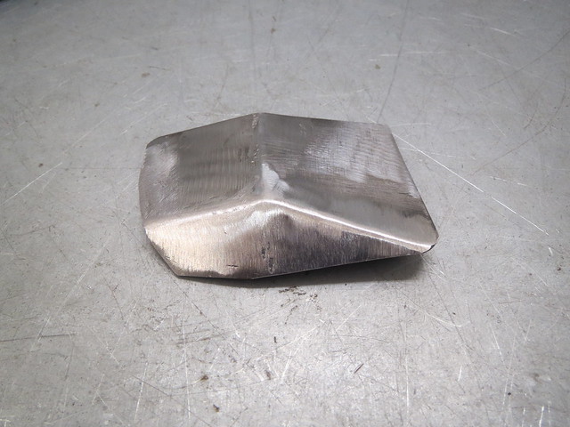
Both shapes were transferred to 2mm sheet before the rear one was cut and bent to shape before being welded. They were then loosely bolted into place to make sure all was well.

Image

Image

As I was happy with the fit, the suspension bracket was fully welded to the chassis rail. I guess I'd missed a bit of oil or something, as one of the plug welds needed cleaning back.

Image

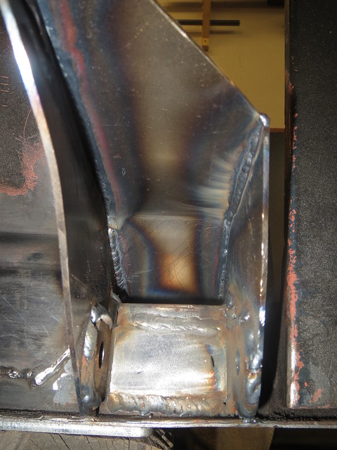
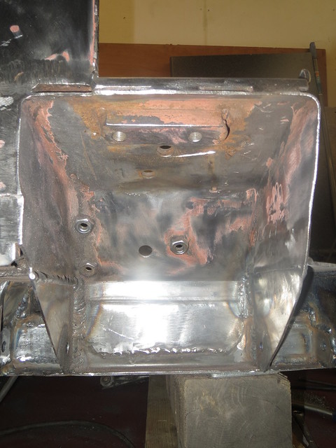
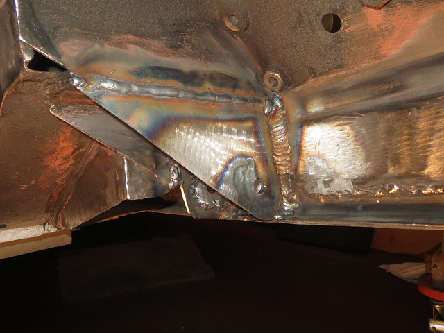
The rear reinforcing plate was then welded in. Some of this took a while as I could either see the weld or get the torch in, but not always both. The vertical weld against the chassis rail on the back of the bracket was the worst one to do. The welds have yet to be cleaned back, but they will be to make it look cleaner.

Image

Image

The front plate was much easier to fit.

Image

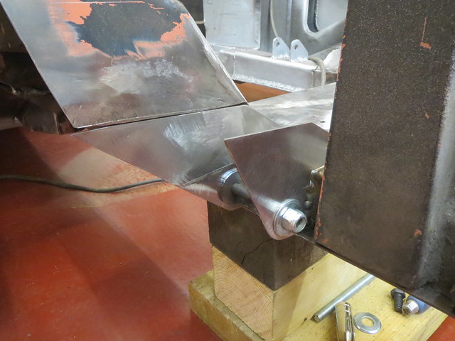
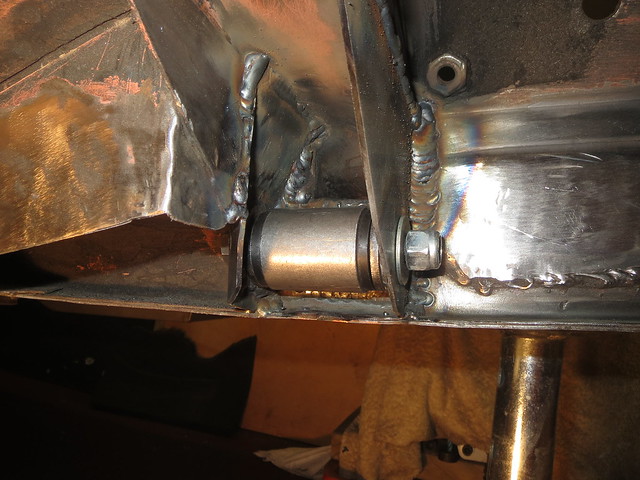
With both plates in, I was about out of time before dinner, but there was just time to fit have a trial fit of one of the suspension bushes. Whilst the rear plate looks like it blocks the bush, with the angle the wishbone tube will run there is plenty of clearance.

Image

Monday, 17 November 2014

More front end progress

With some more thought and planning, as well as seeing JLH's front end as a sanity check, I was happy to get stuck in with the cutting discs and the next step of the front end. JLH are a small local company that specialise in Morris Minors, but are starting to branch into Spridgets too with go faster bits.

I say sanity check, as I had been thinking about where to put the coil over. As I imagine JLH found out, the only sensible way to fit one of a good length is to remove a chunk from the front of the suspension tower to allow one to get near to the plate the lever arms normally bolt to. I have seen short ones fitted up into the tower where the coil spring normally sits, but for a road going car that won't work well. I was a bit worried about cutting so much from the outer edge off, but as John has already done what I was thinking of, I now feel much happier about wading in. I just hope he knows what he's doing...... ;)

Before I got too stuck in, I wanted to cut the remaining bits of the front support brackets off. I had thought about keeping them, but when I sat and look at them in more detail, it's just not worth it as wider ones will do a much better job. To give better access I also cut the steering rack cross member out, as it's welds are cracked and it was going to have to come out at some point anyway. Now just helps make things easier.

Image

This shows the line that I plan on cutting the tower back to. I expect this to cut back into the upper spring mount, but how much I'm not sure yet.

Image

This shows the first level-ish cut made and how far into the spring mount it's gone.

Image

With the now accessible welds ground back, I'm left with a fairly level surface to which I can weld a reinforcing cover plate as well as seam weld the tower where I can get to it. This plate will tie everything back together with in the tower itself. There will then be a second plate to link across to the upper left hand A arm mount, which will be set back into the triangular frame to the left of the tower. The box for the mount will be the full depth of the frame to make it as strong as possible. I won't be fully closing the lower edge of the spring mount to the cover plate, as the big hole in the bottom will be act as a drain should anything get in.

Image

Before I can put the cover plate on I will need to sort the lower support brackets out, as well as clean and paint the inside of the tower, as the plate will limit access to the bits I need to weld. I suspect I'll have to make the brackets on the car from sheet, as I doubt I'll be able to make them in one piece on the bench.

Saturday, 8 November 2014

Finally making a start on the front end

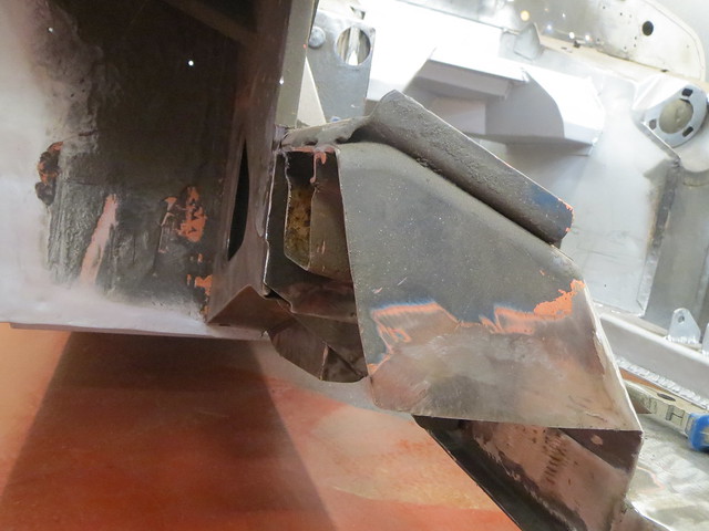
With the rear suspension complete, although I am still to check the wheel clearance, it was time to make a start on the front end. But first I needed to cut the existing brackets and supports back to match what I had already done on the LHS of the car. The RHS looked like this some time ago:
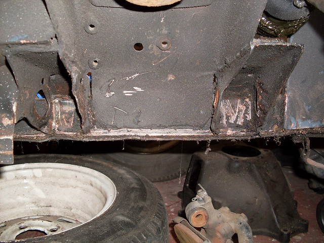
Image

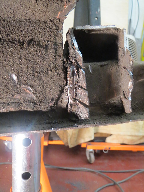
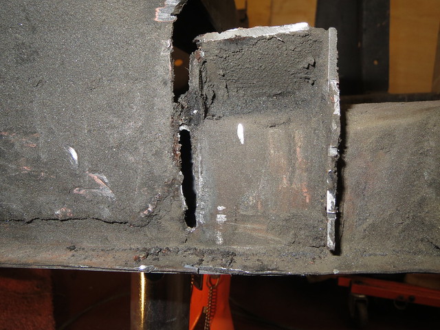
I started off cutting back the front bracket and it's supporting plate back. But I soon ran into an unexpected, but minor, problem. Part way through cutting the bracket back, I found that it was both cracked through above the chassis rail, and on the verge of removing itself from the rail altogether.
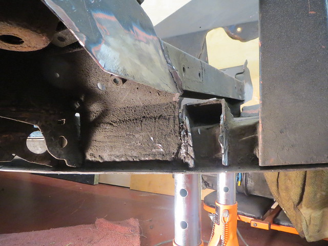
Image

Image

Image

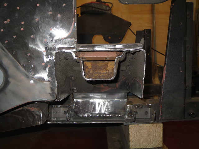
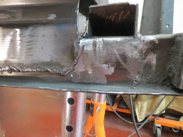
Thankfully, the tear is almost on top of one of the inner webs that I fitted when I straightened the rails so welding it up was nice and easy.
Image

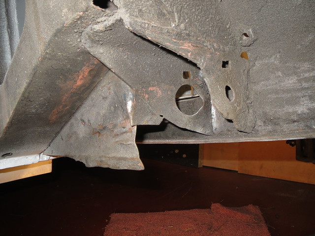
The rear half of things was next. It started off looking a bit worse for wear:
Image

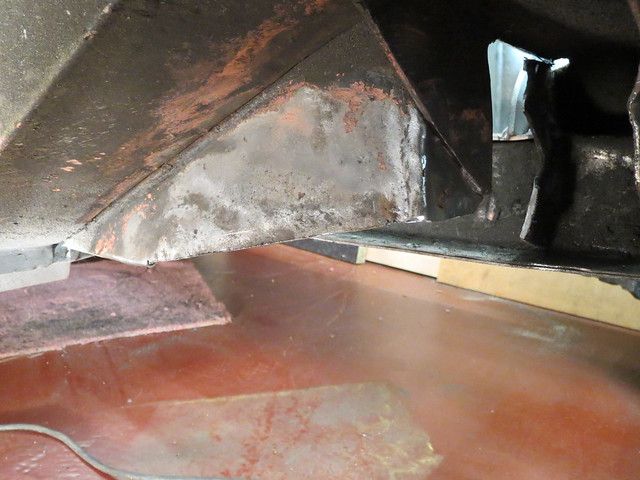
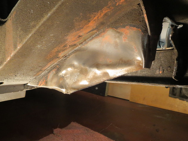
Once I'd cut back most of the unwanted sections, and given it all a clean up there was the rippled section left to flatten. The remaining bits were then cut back as far as I could get them:
Image

Image

Image

So now I had a good clean base for the suspension. This side will be built up and checked as thoroughly as I know how to before using it to make a jig for both of the suspension arms. That way I can ensure it's all even, and should I ever bin it I can make new ones easily. Before I could start with the brackets on the car, I wanted to make sure the hubs and wheel fitted together ok. They're also needed to measure the length needed for the lower arm, as it will be determined by the track width.

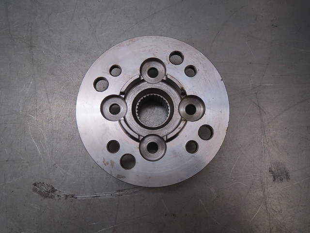
The front end is based on the uprights/hubs of a classic mini, but using the later Metro drive flanges as they're bigger. The usual PCD of a mini/metro is 4 x 4", ie 4 wheel studs spaced evenly on a 4" circle. My rear suspension, and wheels, use the Ford pattern of 4 x 108mm. Small differences can be taken up with special bolts, but the 6.4mm difference I have is too much for that. So the only real option is to re-drill the drive flange to suit the wider spacing. This isn't something I was willing to attempt, as the holes must be bang on and very closely sized to the splines on the new studs. But thankfully there's a local place that was happy to alter them for me, as well as trim my CV joints down to save some extra weight.
Image

Image

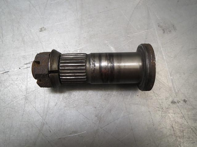
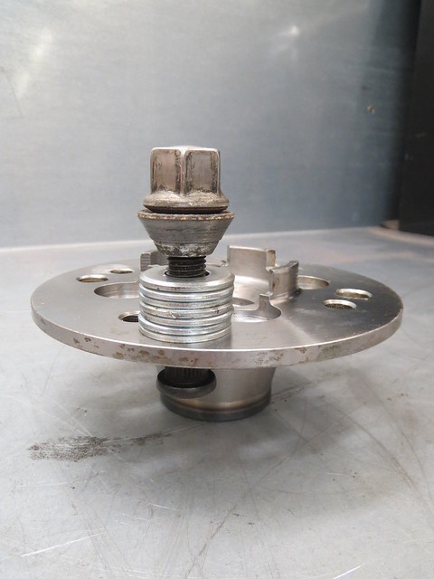
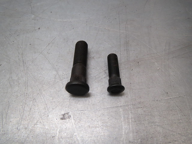
The next thing to do was to fit the new studs. The mini studs are 3/8" where as the new ones are M12, so quite a bit bigger. Which is a good thing as the Sprite will have a top speed well in excess of a mini! The easiest way I know of to fit studs is to go find a man with a press, but by this time all the local garages were shut, so I used a more manual method using a spare wheel nut and some washers. As the nut is turned the stud is drawn into the flange.
Image

Image

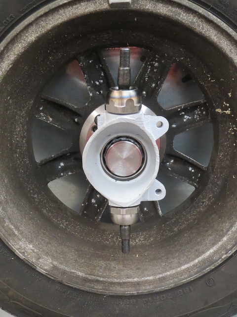
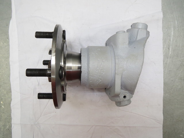
With all eight studs fitted, bearings were fitted to the upright. These are just plain ball bearings for now, as I'll be using the better, but more expensive, taper roller bearings for the final build up. The same is true of the ball joints, cheapo versions for now. The axle stub then goes in before putting the drive flange on. It looks a little long once assembled as the brake discs sits behind the drive flange. And as I'll be using 10.75" MGB discs they'll be an adaptor to match the threads that sits between the flange and disc. I'm using the hubs swapped side to side, as a mini has it's steering rack behind the wheels, where as the Sprite has it in front. This stops the brakes and steering trying to share the same space, but has no effect on the suspension itself.
Image

Image

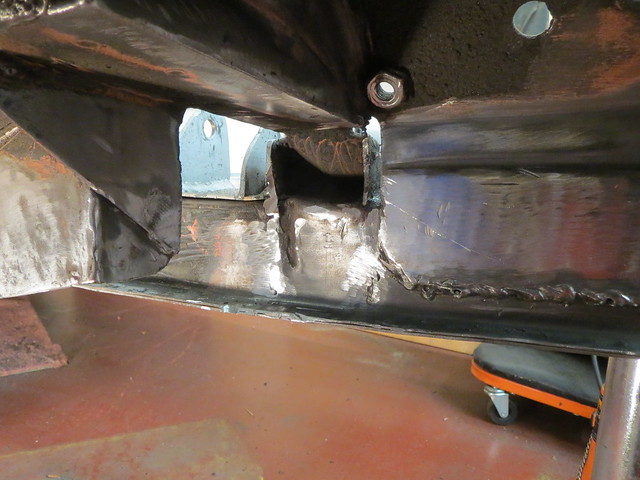
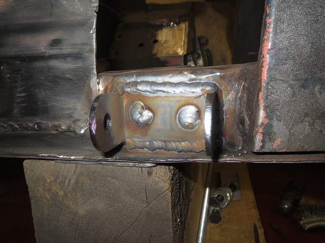
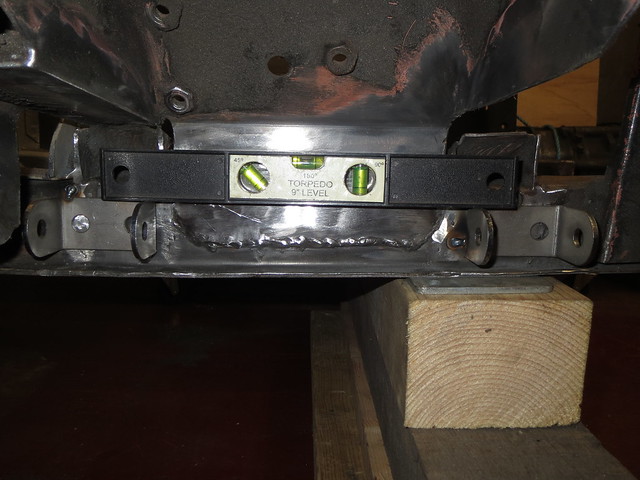
So the front uprights were now fitted and I was happy with that end of things. And that meant the last thing to do today was to spend a while levelling the suspension brackets and tacking them in place. I say levelling, as the front chassis rails kick upwards on a Sprite by 1" to give extra castor. However, my set up won't need that so the brackets are level to the ground and not the rails, hence why they look wonky. The brackets are also fitted as wide as possible, given the webs hidden inside the chassis rail. This gives the strongest possible base for the lower arm without completely re-building the front end again.
Image