Search This Blog

Monday, 22 September 2014

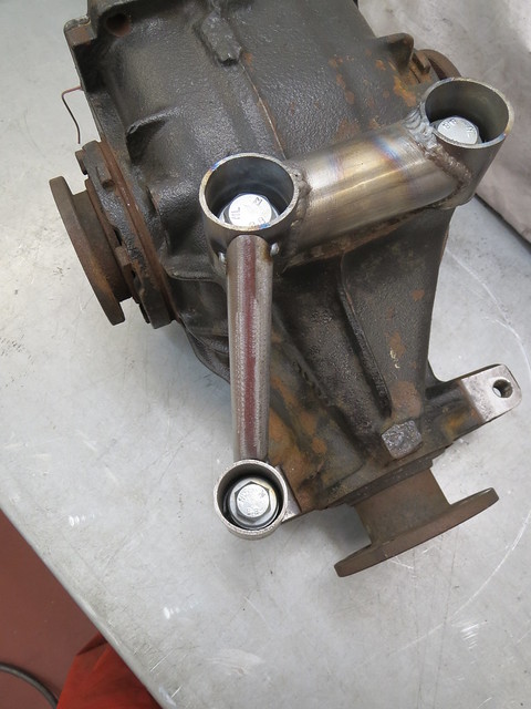
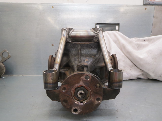
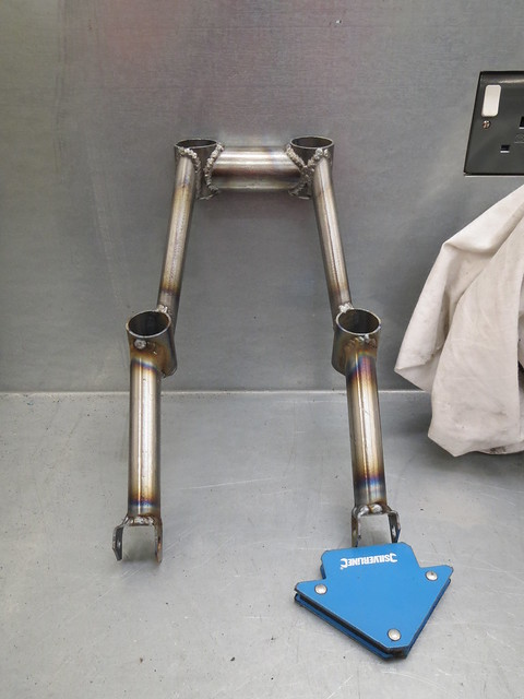
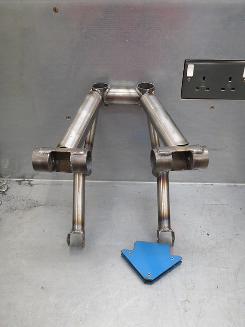
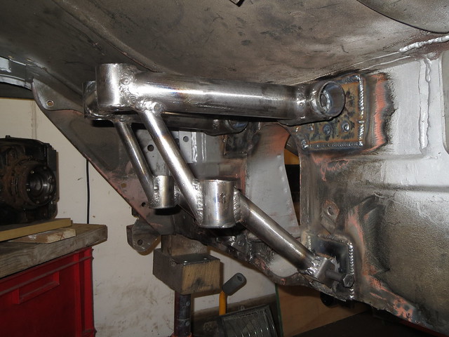
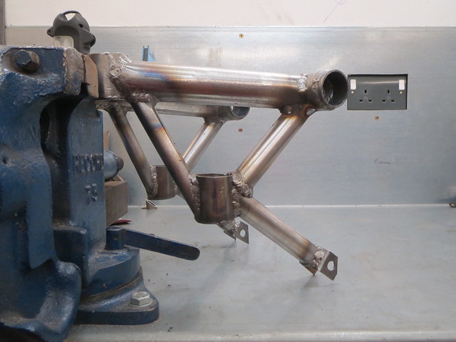
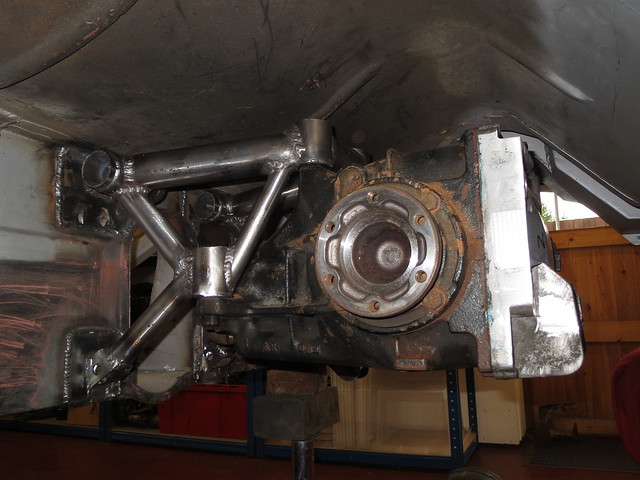
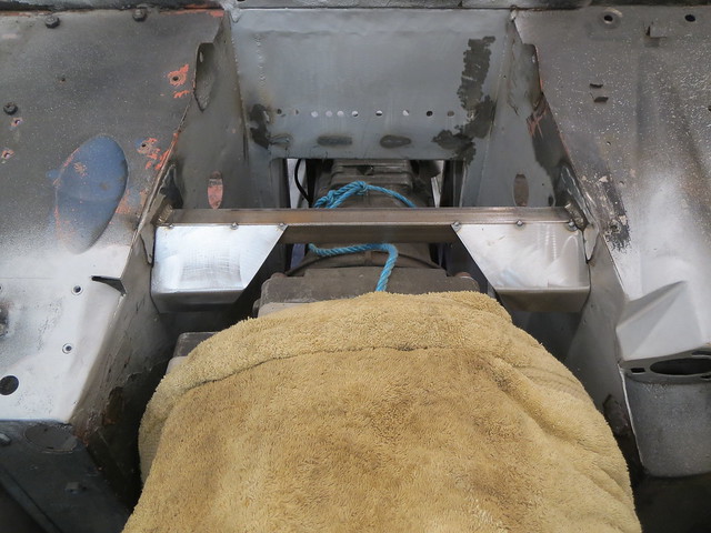
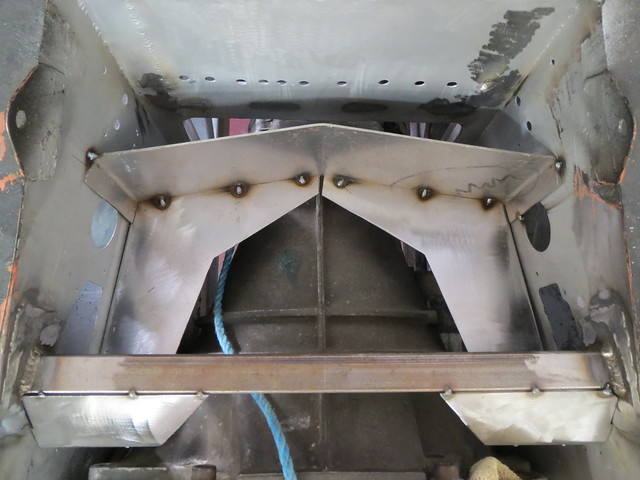
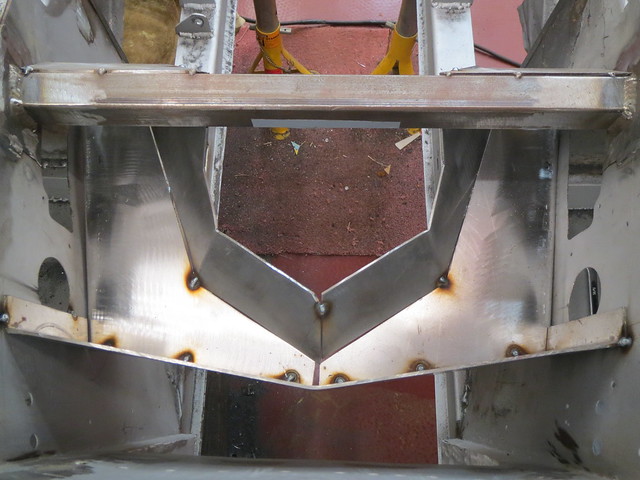
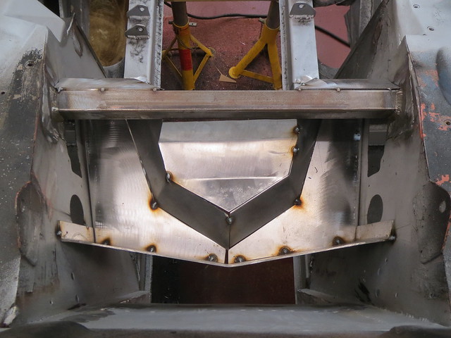
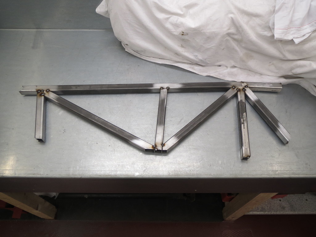
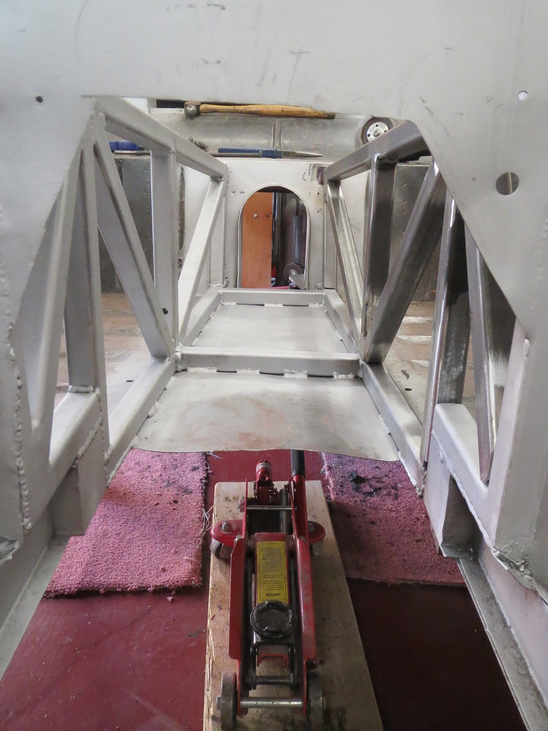
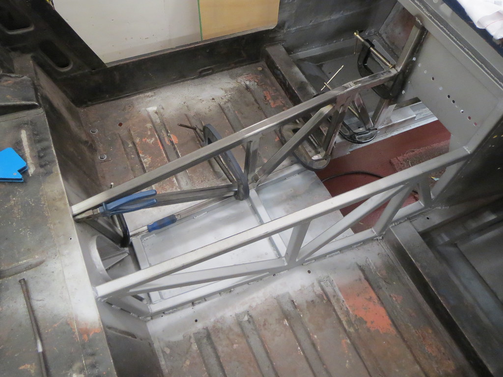
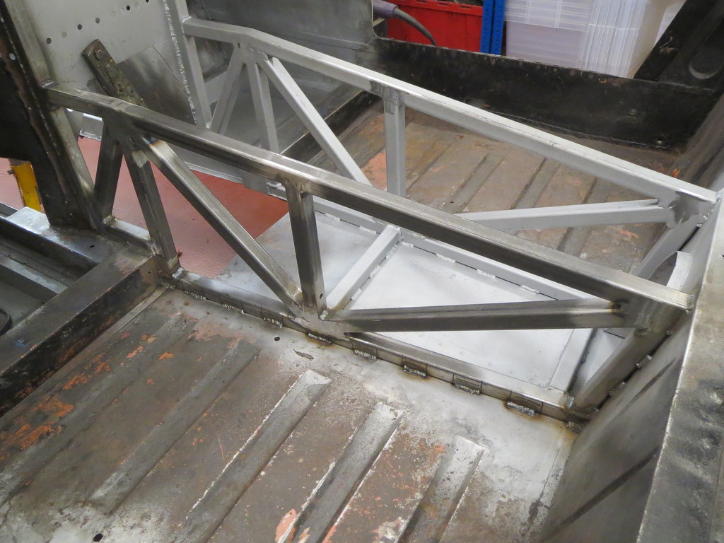
The completed diff cage.

I thought it best to put the final stage in the diff cage up now the fabrication is complete.

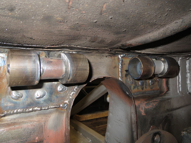
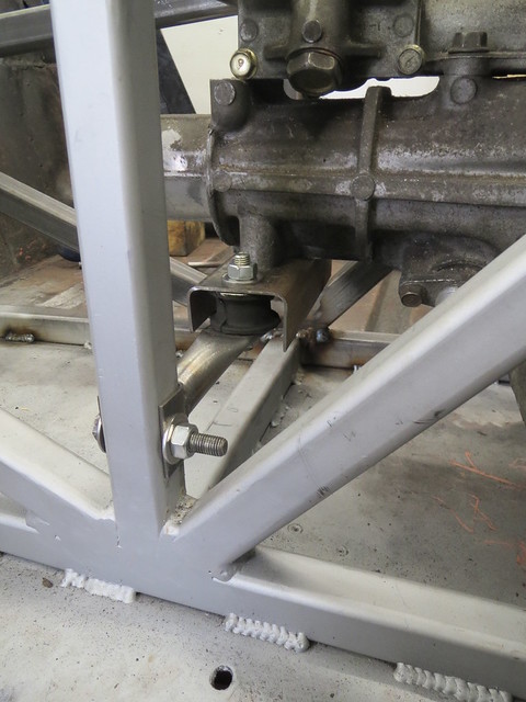
The cage had the lower mounts cut off so I could make new thicker ones. Where the first ones were bent pieces of steel, the second versions have bee cut from 2mm thick 40mm box section. This makes them much easier to build as well as being stronger and thicker. Being wider, they will require washers inside them to prevent any crushing, but it also means that I can alter the positioning of the legs slightly too.


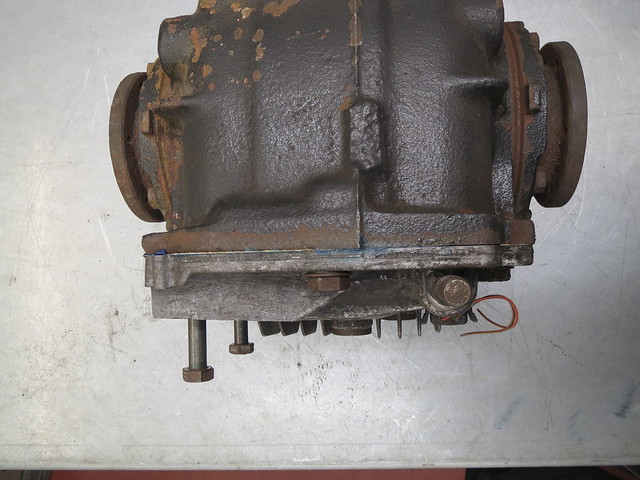
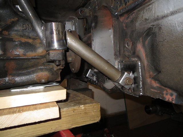
with everything bolted in place, the diff was levelled out as it was hanging tail down a touch. This did open a small gap between the legs and the mounts, but nothing wide enough to worry about with MIG welding. And so it was tacked in place on the shell before welding fully on the bench.


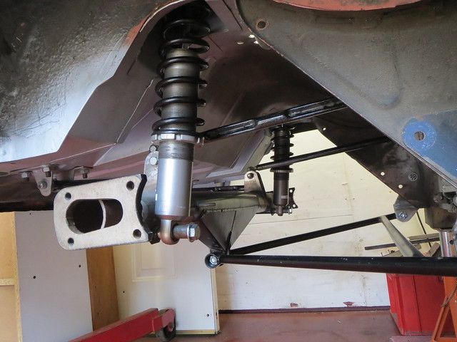
So the diff cage was finally completed. With the diff now in it's final place I could refit all the suspension to check for clearance. Before the diff was levelled there was a small gap. With it levelled and bolted in tight, there was no longer any gap.


So the final step in fitting the diff is to cut the cooling fins down a touch to create some space. I had expected to shave a little off the outer fins to clear the A frame link, but it looks like I'll be trimming them all back.

Friday, 19 September 2014

Diff cage

Since this has proven to be more involved and complicated than I had first thought, it gets it's own update.

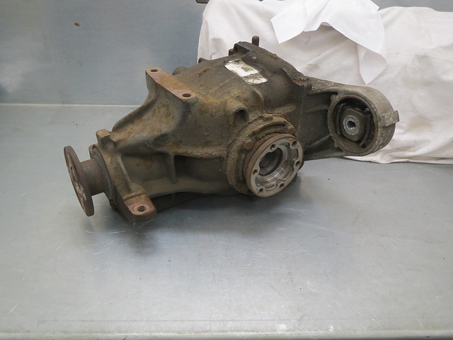
Once the diff was given a quick clean and a wire brush, it was time to start modifying the casings to better suit my needs. As standard the diff has five mounting points. Four that are hard bolted at the front and one large rubber mount on a wing on the rear cover.


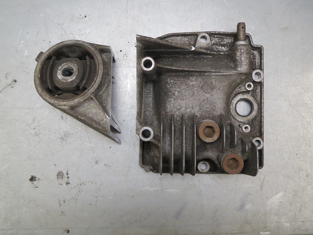
Whilst all five mounts are obviously used in the BMW, the rear wing gets in the way for what I want and I've no where to mount it anyway. So the rear cover was taken off, partly so I could clean the diff out and partly so I could cut the cover down without damaging the diff at all.

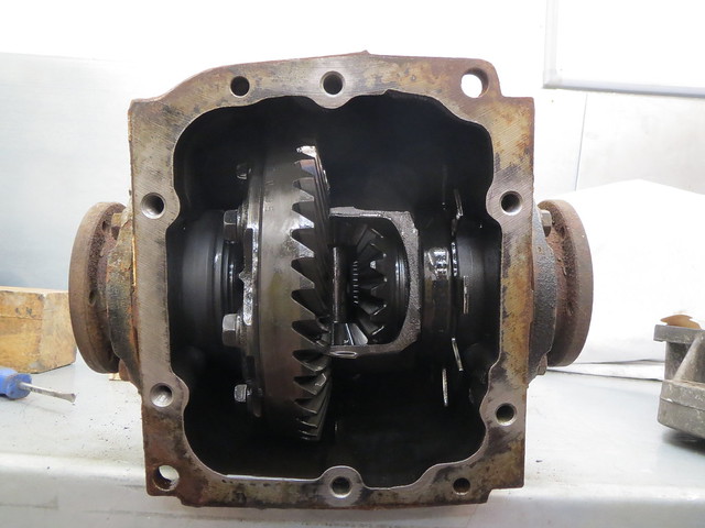
The inside of the diff looks largely as you would expect, but with one minor difference. BMW use the diff to mount the speedo trigger, and as such it has a fan on one side to trigger the sensor. I'm not sure yet if I'll keep this or not, as I may use something on the prop or maybe a front wheel. The diff is easiest as BMW have already done all the R&D for me and the sensor is reliable. The prop gives a better indication of rear wheel speed, as it measures total wheel spin better but will require me to mount a suitable sensor. The front wheels give a better idea of road speed as they don't react to wheel spin, but are easily the hardest to make work.


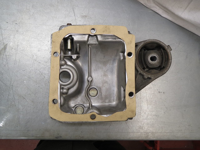
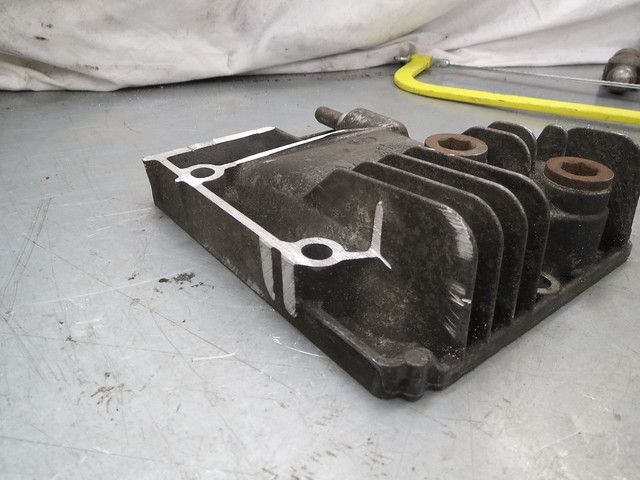
So now to cutting the rear cover down. This was done in a few steps to ensure I didn't over do it or bugger it up! The first step was to clean the cover up and make a new gasket for it and then cut the meat of the wing off.


And then the remaining metal was cut down and the two bolt mounts cut back and sanded flat. I did later sand the edge of the cover flat too just to make it more complete.


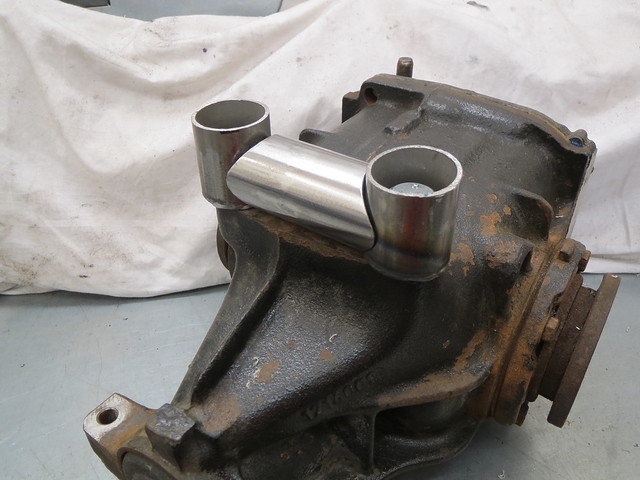
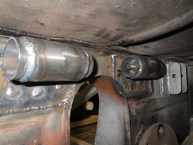
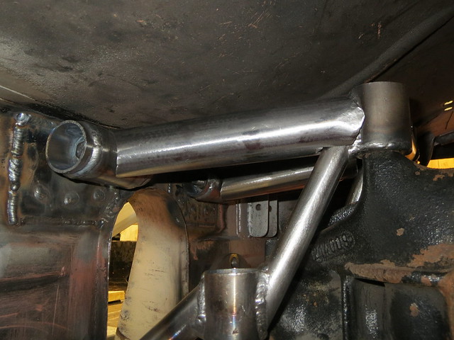
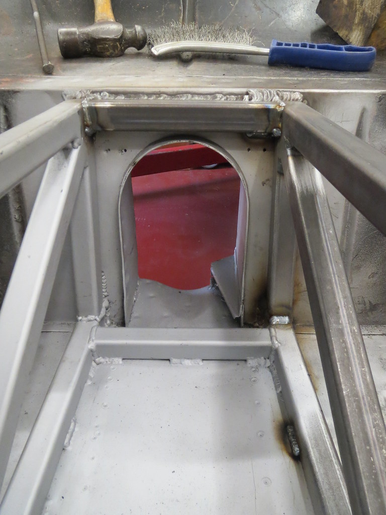
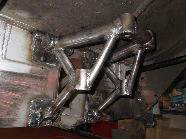
So now the diff was cut back I could get on with the cradle. The first thing to do was to make the diff side of the frame. This would then allow me to accurately measure up for the tubes to the transmission tunnel mounts. This is a story best told in pictures.


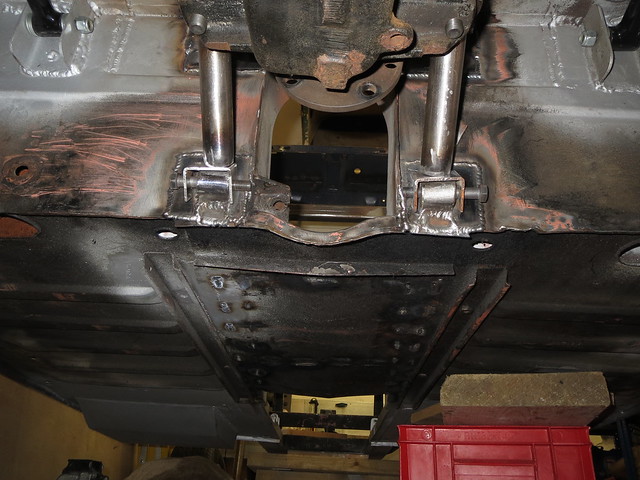
So with the diff side of the cage completed, the diff was positioned against the shell to sort the lower legs.


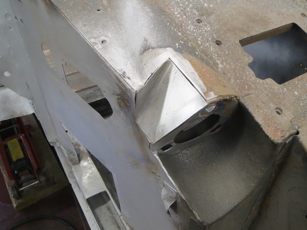
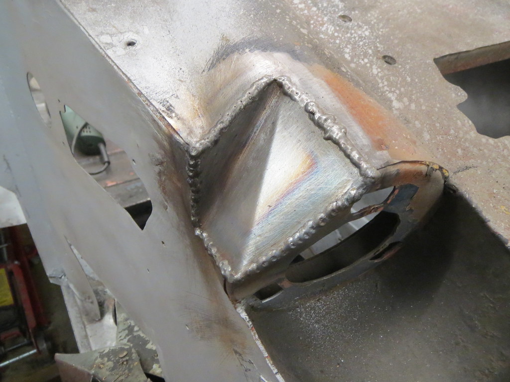
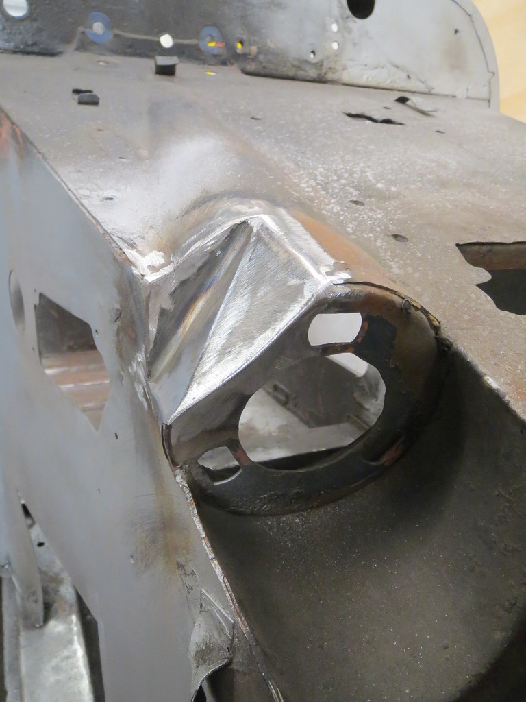
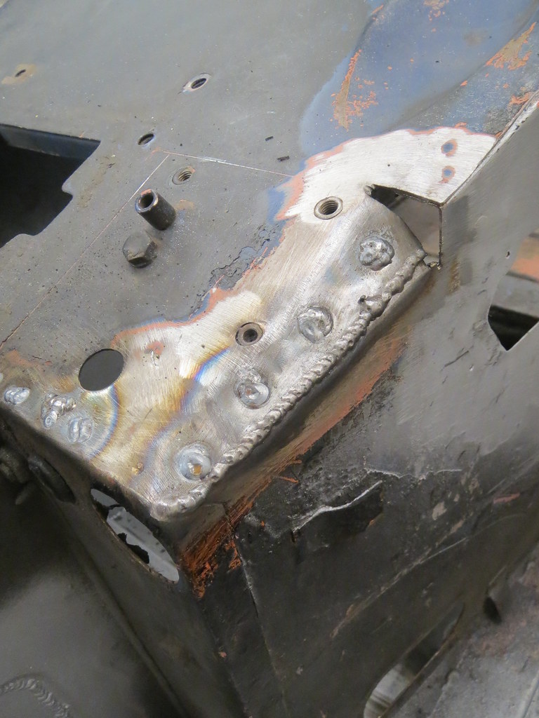
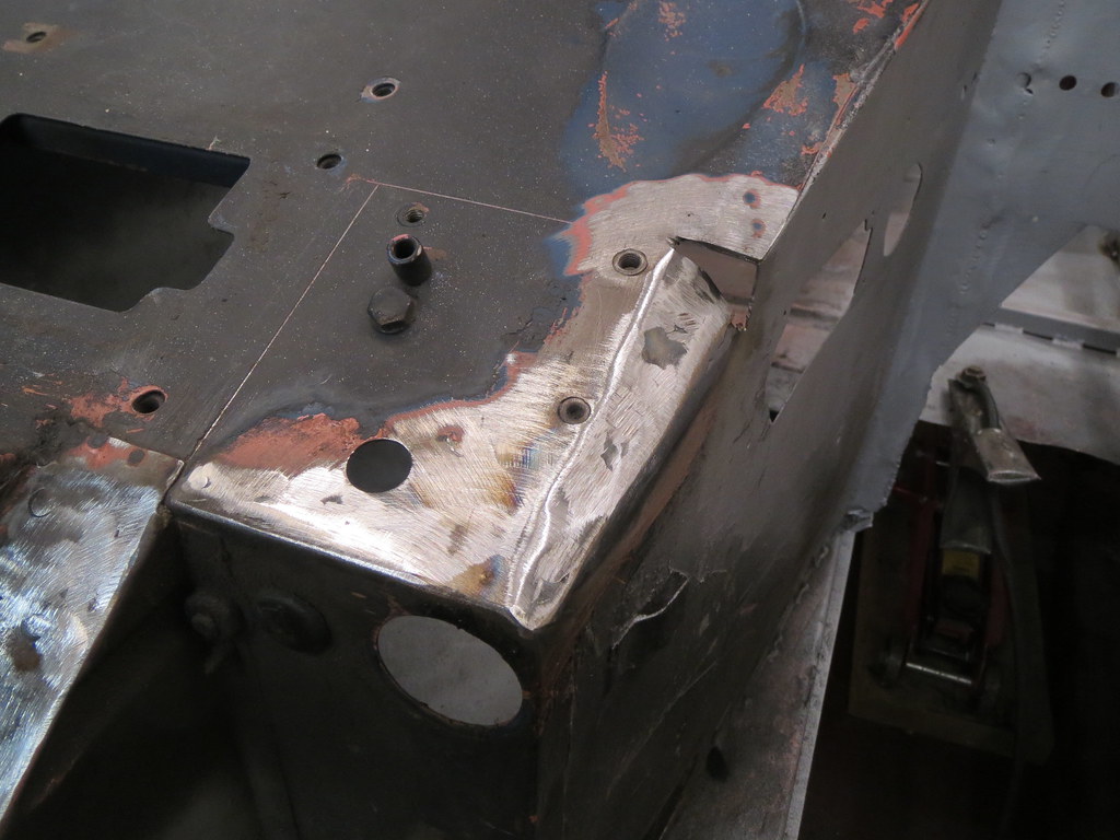
The next problem was how to match a piece of 1.5" tube against a mount that was about 1.5" wide. My solution was to make the mount wider, but in a way that allowed the extra width to not get in the way.


And that is as far as I've got with it. Due to all the heat from welding, the lower leg mounts have skewed upwards by 4-5mm, so I'll need to cut the lower mounts off and re-do them. But that means I can also make them a touch bigger and stronger, so that's no bad thing.

August and Septemeber updates!

I'm really not doing well with keeping this blog up to date! Which is going to make this update a bit full.

But first things first. The heater tray was fully welded in, cleaned up and then etch primed. The lower flanges were spot welded from within the foot wells and then cleaned back to hide the welds. The top plate will will be done when I'm ready to get that far. But I'm happy with how this all looks for now and it still allows the engine to fit easily. Or as easily as a 2.5l V6 will in a Sprite!


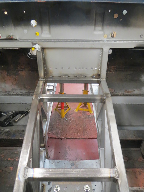
The next step was to get cracking with the rear suspension and get more done on the back end before moving on to the front. So the first thing to do was to actually finish the transmission tunnel off and get the plates fitted to the rear bulkhead face to help strengthen the diff mounts.


I've not got a photo showing all four plates welded as yet, as the bits over the top of the upper mounts hasn't been done. I tried doing one of them, but the very restricted access makes it virtually impossible to see what I'm doing, so those bits can wait until I next roll the shell over.

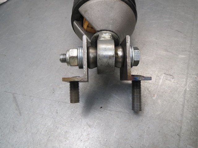
But with the plates as in as they can be for now, I had a look at the suspension itself and the brakes. This first meant getting the coil overs hanging in place so that the linkages would all hang under their own weight. So I made a set of top brackets for the coil overs and got them bolted in place, only to realise that the lower mounts on the coil overs, which I hadn't really looked at before, take a 10mm bolt whilst the De-Dion tube takes a 1/2" bolt. But as a temporary fix, I've removed the misalignment washers so I can at least clamp a 1/2" bolt in place for now. The thread lengths are different on the top mounts so I can fit them more easily as I have to do it with one hand feeding the coil over in from below whilst trying to put a washer and nut on from above. This was I can locate them one thread at a time.


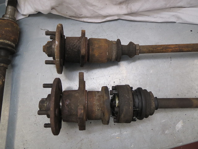
With that done, the rear suspension was now intact at last, and I could get the hubs in place.Only it very quickly became apparent that the disc brake drive shafts and hubs that I have don't fit the De-Dion ears that I got hold of! Arse. I know this isn't a problem with the ears, as the design of them hasn't changed. So following yet more research, it turns out that I should have used the smaller drum brake hubs and drive shafts. So back to Ebay it was!


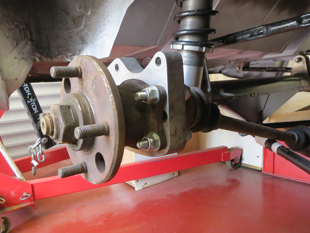
And once I found a set of shafts and hubs, I could actually get the hubs bolted in place and the callipers on the ears too. Only to find that the brake discs I had been planning on using are too big. Thankfully, this isn't a big problem as the right discs are only £25 or so each, even from Caterham! I can still use the discs I have to measure up for where the wheels fit and what not as they still move the wheel outwards by the same amount.

This photo shows the difference between the two types of set ups. The main difference is the width of the CV joint. The drum brake tripod joint is much slimmer. This also means it's lighter, which is a good thing.


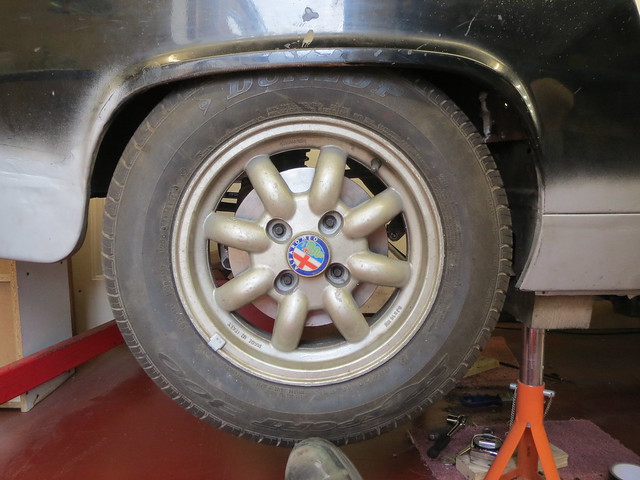
And whilst I know they won't fit, as the tyres are too wide for the arches, I couldn't resist trying a wheel on for size. I quite like the way it looks! Just need to see how much surgery is required to make a square wheel arch shell accept a 185 section tyre.


So following the sense of achievement that seeing a wheel on the car for the first time if four and a half years gave me, I had to spend far more time than I wanted to carefully measuring clearances so I could make a start on fitting the diff. But as that's quite involved, I'll put that into it's own update.

Wednesday, 30 July 2014

July's update!

Once again, I've forgotten all about updating this blog!

Much has happened in the past month, and I'm please with the progress.

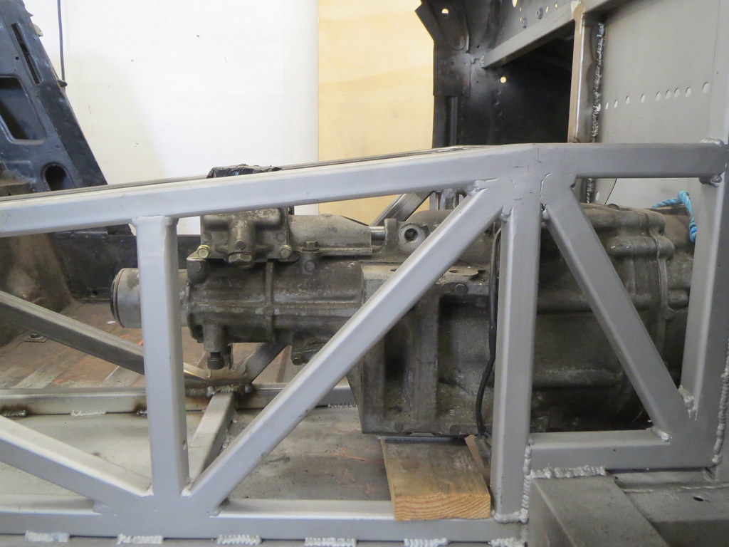
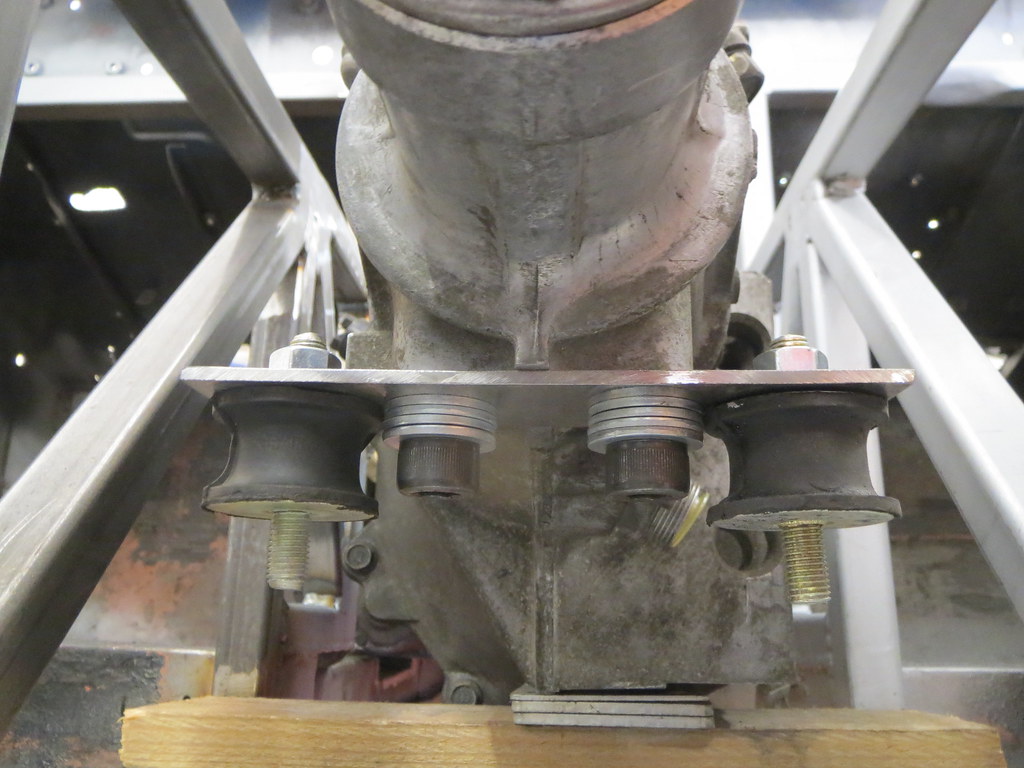
The gearbox mount was completed, but found to have a bit too much vertical deflection in the flat plate across the gearbox. So a simple fix was to replace it with a shaped piece instead.


There is now less than 2mm vertical movement with my 100Kgs stood on the tail of the box!

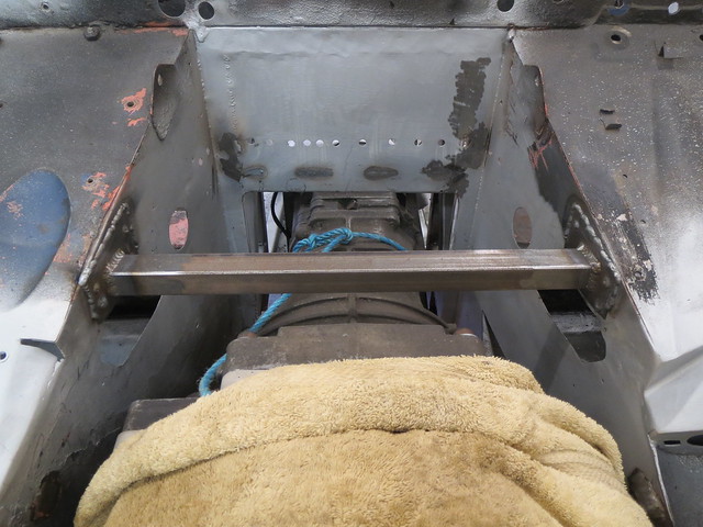
With the engine and box now fully mounted, more work on the tunnel was done.

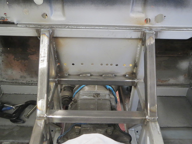
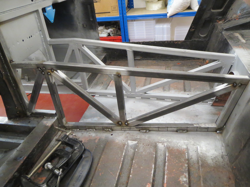
First the cross tubes were fitted:


And then diagonals from the frame up to the dash tube:


For now, that's the tunnel completed! I still want to add diagonals that go from the front bulkhead up to the dash tube, but I need to have the dash and steering column fully mounted before I go ahead and do those in case of clashes.

The next thing on my list was to do some more work on the rear suspension, specifically mounting the coil overs at last. The first step was to make the top mounts. This are just simple pieces of 3mm angle, with a section of M10 threaded bar welded into place. One side is longer than the other to aid with locating, as the coil over needs sliding up into the tower from below with one hand, whilst trying to get a nut on with the other hand inside the car. With one peg longer, they can be located one at a time. As clearance is tight, I also need some shorter bolts.


One problem with the coil overs I have is that they have cone shaped washers, with a 10mm hole as that's what Caterham use on the CSR. However, the De-Dion tube is designed to take a 1/2" bolt, so the washers have to come out, but that leaves a 15mm hole! I'll need to sort something out for this later on, but for now I've just made up a spacer using a 1/2" nut so I can check everything fits.


With both sides done, the rear linkages are all now hanging under their own weight for the first time! Once I get hold of a set of the end brackets or ears, I can make a start on hanging the hubs and so on before getting the diff spider made and fitted.


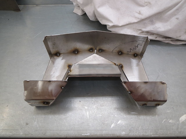
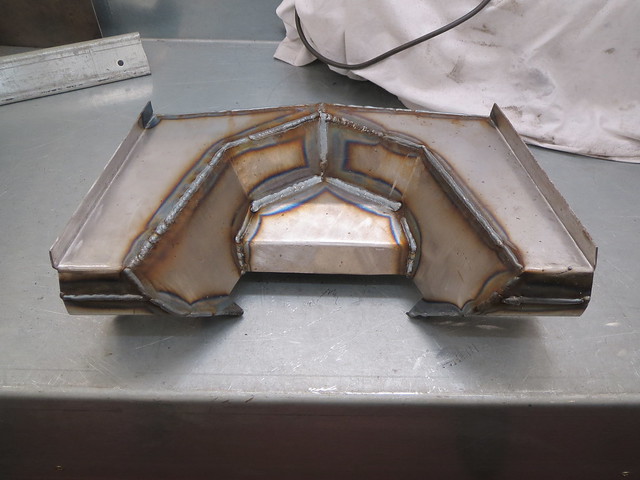
Since I was feeling all good and optimistic, I decided it was a good time to tackle the heater tray. The original was cut out ages back to allow the engine and box to fit. And now they're mounted I can make a replacement for it. It was also a chance to create a little extra rigidity in the foot wells.

The first thing to do was to fit a length of 1" box between the footwell panels. It had 16 SWG plates added to each end to spread the load.


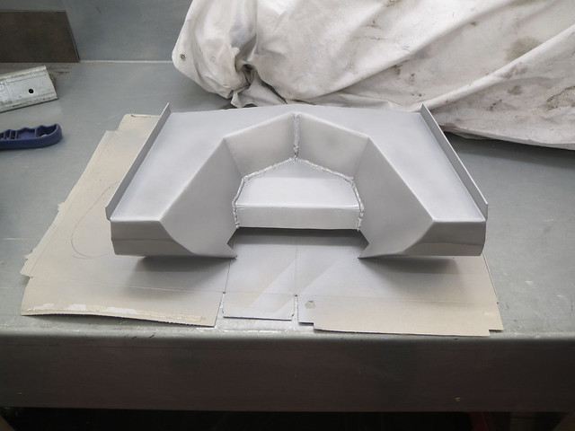
This then gave a fixed point to work off for the leading edge of the tray. The plan was to make each section as a card template, before reversing that template for the other side, like this:


With the whole thing tacked together, it could then be removed from the shell as one piece and welded up on the bench:


Once cleaned up, the whole thing was given a coat of primer and left to dry.


And that's pretty much where I am now. The tray is about to go back into the shell, but I've got the spot weld holes to drill first.

On another note, I'm still trying to find a set of seats that will sensibly fit into the space I have for them. For a seat roughly 600mm long, the front can only be 460mm wide. This is smaller than the vast majority of seats so finding something second hand may be hard work. I might even have to resort to buying something new!! Or just use GRP shells for now as I imagine I'll only be carry adults whilst I get the car reliable. I'm not sure which will work out better in the long run. Not that there's any rush to decide, mind you!
Sunday, 29 June 2014

Yay, engine and box back in at last!
So a few more weeks have gone past, my best mate is now married to his beautiful bride and I can get back to work on the Sprite!

From where I left off with the frame, I got the second side cut and tacked into place. I then decided to cut the entire side out and weld it on the bench. This means I can do all the welding the right way up, but it does mean a bigger hole in the bulkhead so I can fit the diff mount end of the frame in.


Before it was welded in, I fitted two of the lower frame tubes before access became awkward round the frame. The rear most tube should be hard up against the bulkhead, but I decided that the work needed to do this wasn't worth the effort. So the tube sits roughly 1" forward of where it should be.


The only bit of the frame I could safely fit for now was the rear top tube, against the bulkhead. The welding needs tidying up as yet, as I had the bulkhead hole to fill in slightly.


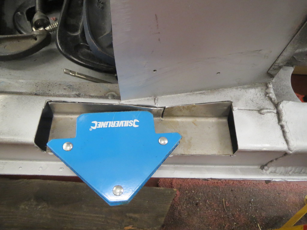
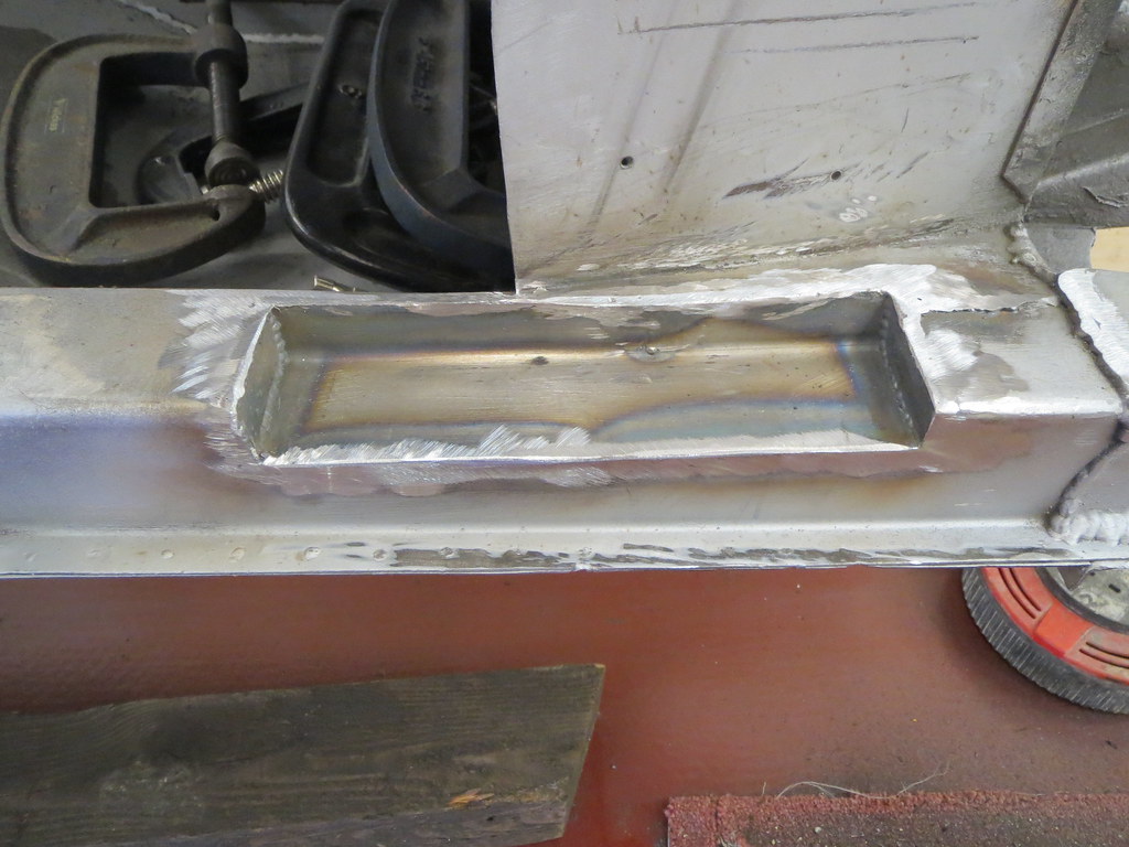
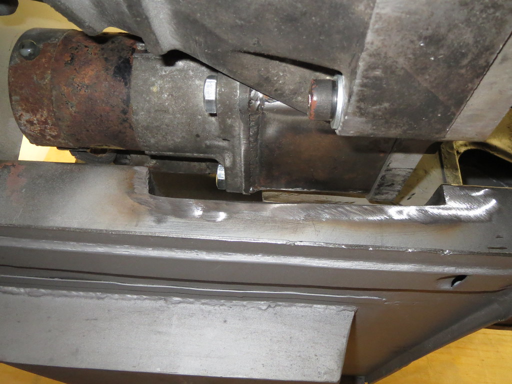
The rest of the frame tubes had to wait until the engine and box went in, as I knew some may sit in the same place as the box. However, before I could fit the engine and box, I needed to close off the footwell tops and the chassis rail notch.


I've left the small infill piece out of the RHS footwell for now as it might come in handy for running cables for the ECU, since it's so close to the engine.

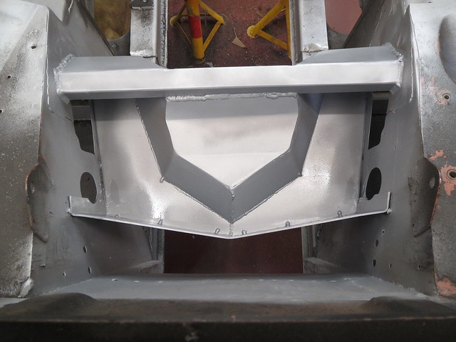
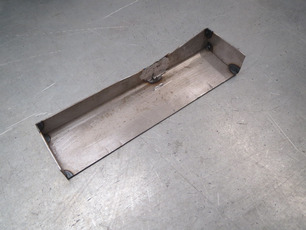
The chassis notch took a bit more time to do, as I had to form an odd shaped box:


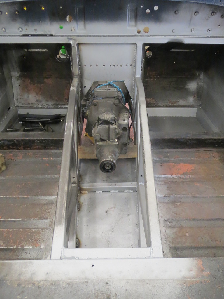
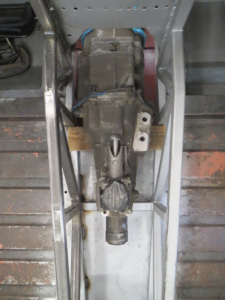
And so I could get the engine and box back out from under my bench and into the shell. Thankfully, there's loads of room round the gearbox. I haven't checked the heads yet, as that can wait for a quiet evening to do.


It's just as well that I decided not to fit the other cross tubes, as the next one forward would only just miss the gear turret. The other would fit above the box though. I also have space to partly replace the chassis cross member with a lower version, which is good news.

The next thing to do was the gearbox mount. This is a Mk1 go at it, as I'm not sure if this is the best way or not yet. I'd like to be able to screw the bobbins straight to the box, but I can't find any with an M10 x 1.0mm thread.


The frame bracket is formed from a strip of 2mm sheet bent round an off cut to give a good fit. I ran out of time to start cutting the tube back to suit, so that's the next thing to do before making a matching version for the other side. I may link the two halves together yet to make it stiffer, but I'm not sure. I'll wait until both sides are done and then see if I can move the box about at all.