Search This Blog

Saturday, 8 November 2014

Finally making a start on the front end

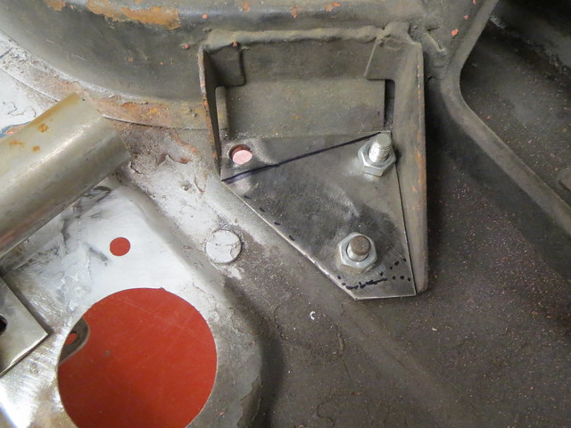
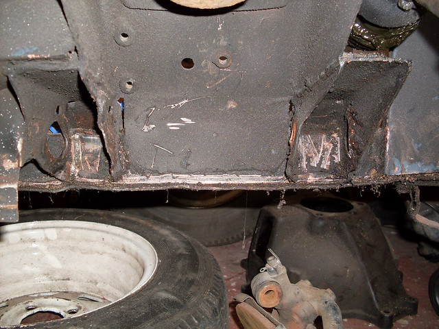
With the rear suspension complete, although I am still to check the wheel clearance, it was time to make a start on the front end. But first I needed to cut the existing brackets and supports back to match what I had already done on the LHS of the car. The RHS looked like this some time ago:

Image

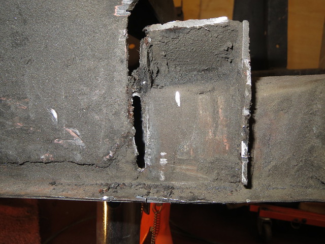
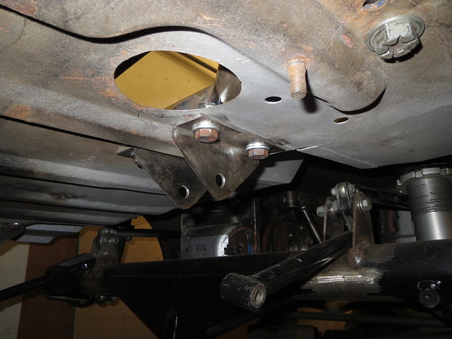
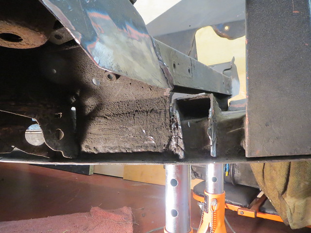
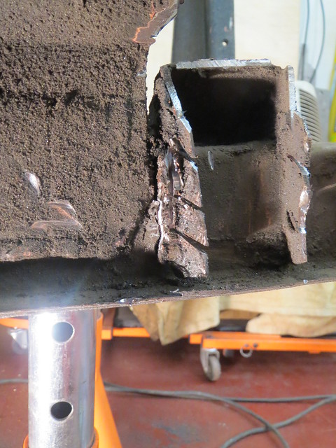
I started off cutting back the front bracket and it's supporting plate back. But I soon ran into an unexpected, but minor, problem. Part way through cutting the bracket back, I found that it was both cracked through above the chassis rail, and on the verge of removing itself from the rail altogether.
Image

Image

Image

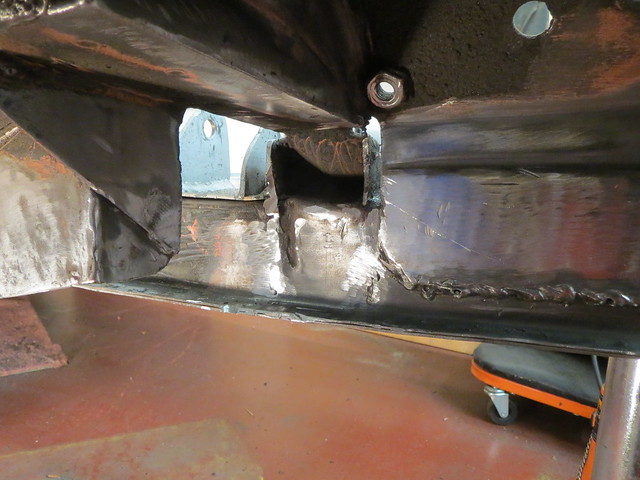
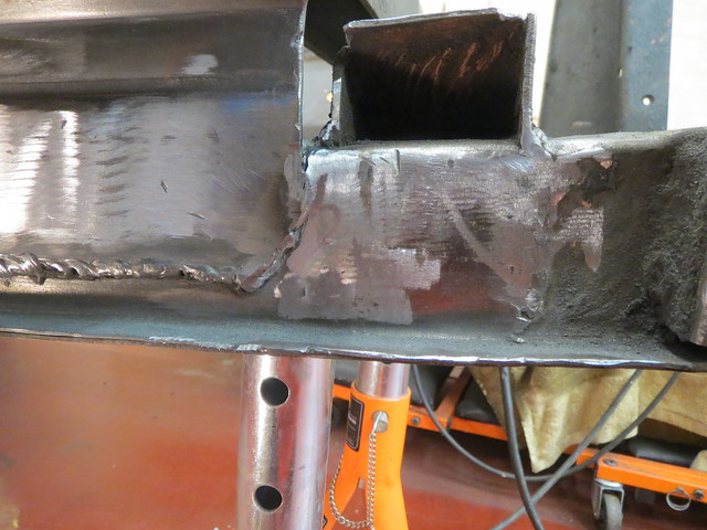
Thankfully, the tear is almost on top of one of the inner webs that I fitted when I straightened the rails so welding it up was nice and easy.
Image

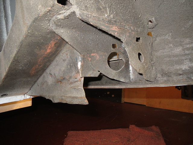
The rear half of things was next. It started off looking a bit worse for wear:
Image

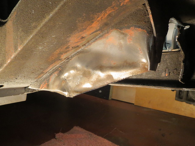
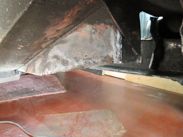
Once I'd cut back most of the unwanted sections, and given it all a clean up there was the rippled section left to flatten. The remaining bits were then cut back as far as I could get them:
Image

Image

Image

So now I had a good clean base for the suspension. This side will be built up and checked as thoroughly as I know how to before using it to make a jig for both of the suspension arms. That way I can ensure it's all even, and should I ever bin it I can make new ones easily. Before I could start with the brackets on the car, I wanted to make sure the hubs and wheel fitted together ok. They're also needed to measure the length needed for the lower arm, as it will be determined by the track width.

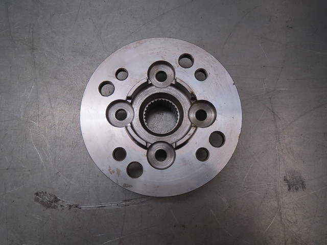
The front end is based on the uprights/hubs of a classic mini, but using the later Metro drive flanges as they're bigger. The usual PCD of a mini/metro is 4 x 4", ie 4 wheel studs spaced evenly on a 4" circle. My rear suspension, and wheels, use the Ford pattern of 4 x 108mm. Small differences can be taken up with special bolts, but the 6.4mm difference I have is too much for that. So the only real option is to re-drill the drive flange to suit the wider spacing. This isn't something I was willing to attempt, as the holes must be bang on and very closely sized to the splines on the new studs. But thankfully there's a local place that was happy to alter them for me, as well as trim my CV joints down to save some extra weight.
Image

Image

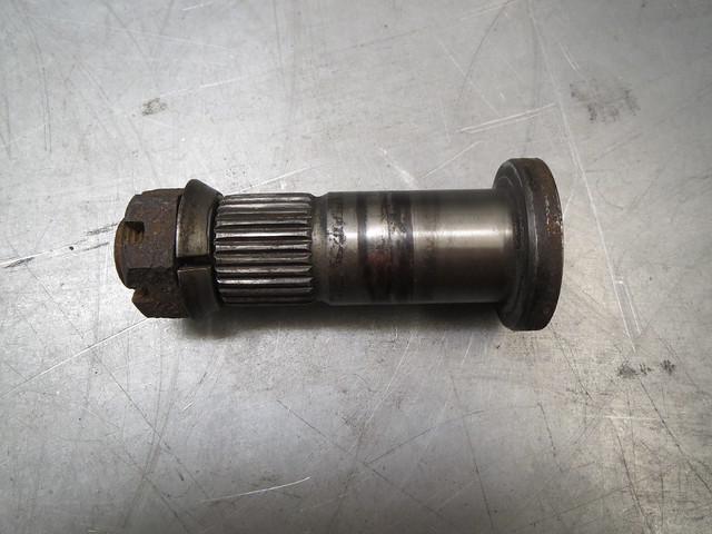
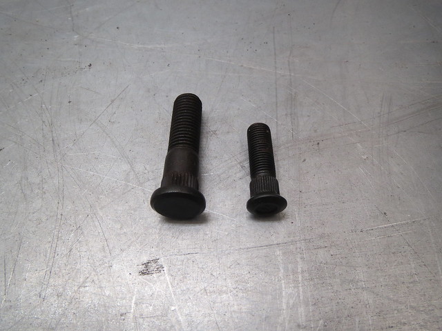
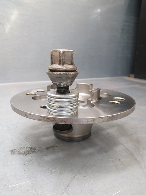
The next thing to do was to fit the new studs. The mini studs are 3/8" where as the new ones are M12, so quite a bit bigger. Which is a good thing as the Sprite will have a top speed well in excess of a mini! The easiest way I know of to fit studs is to go find a man with a press, but by this time all the local garages were shut, so I used a more manual method using a spare wheel nut and some washers. As the nut is turned the stud is drawn into the flange.
Image

Image

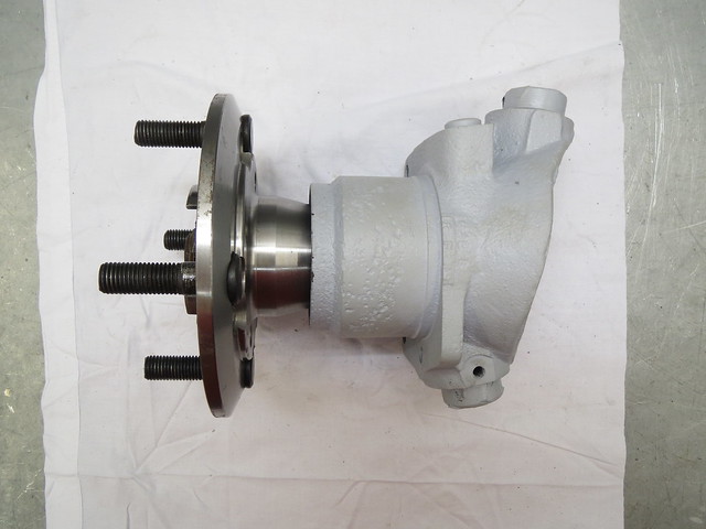
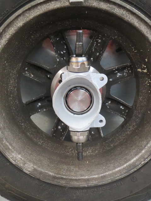
With all eight studs fitted, bearings were fitted to the upright. These are just plain ball bearings for now, as I'll be using the better, but more expensive, taper roller bearings for the final build up. The same is true of the ball joints, cheapo versions for now. The axle stub then goes in before putting the drive flange on. It looks a little long once assembled as the brake discs sits behind the drive flange. And as I'll be using 10.75" MGB discs they'll be an adaptor to match the threads that sits between the flange and disc. I'm using the hubs swapped side to side, as a mini has it's steering rack behind the wheels, where as the Sprite has it in front. This stops the brakes and steering trying to share the same space, but has no effect on the suspension itself.
Image

Image

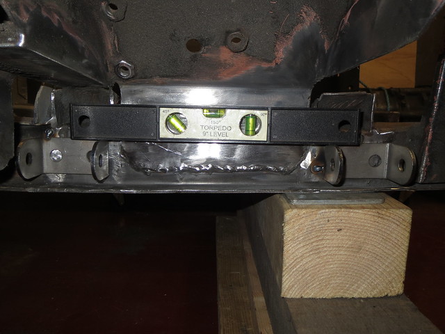
So the front uprights were now fitted and I was happy with that end of things. And that meant the last thing to do today was to spend a while levelling the suspension brackets and tacking them in place. I say levelling, as the front chassis rails kick upwards on a Sprite by 1" to give extra castor. However, my set up won't need that so the brackets are level to the ground and not the rails, hence why they look wonky. The brackets are also fitted as wide as possible, given the webs hidden inside the chassis rail. This gives the strongest possible base for the lower arm without completely re-building the front end again.
Image

Saturday, 1 November 2014

Yay, I now own a wheelbarrow

So another couple of weeks have passed, and I've been busy working overtime so work on the car has been slow.

Caring on where I left off, the cross brace had to be finished before I could do anything else. So that meant finishing the left hand chassis mount and then linking it to the main cross tube once the tube was squared up against the shell.

Image

I decided to weld the smaller tube to the cross brace first in at effort to prevent any twist from lifting the chassis mount. But it was soon fully welded and bolted back into place once I had checked it for square against the axle hump.

Image

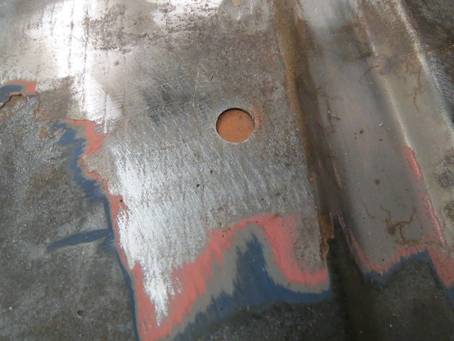
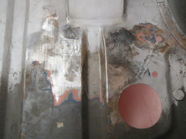
Now the brace was sat in place, I could see which, if any of the existing holes could be used. Unfortunately, only one lined up and even that wasn't 100%. So I decided to weld the holes up and drill new ones. There's a tip I was told once to help weld up small holes in thin sheet. It involves using something I know as a welder's spoon. It's basically a good sized chunk of copper that is used to back the hole to stop the weld dropping away from the panel. It means you can use a lower setting and help avoid distortion in the panel. Copper is used as molten steel, ie the weld itself, won't stick to it. Once welded the panels are ground flat to hide the fact that there was ever a hole there.

Image

Image

Image

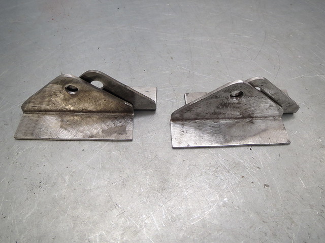
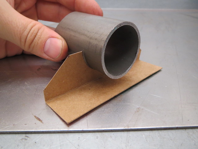
With the boot floor sorted out, I decided to make the Watt's linkage brackets that would hang under the boot before drilling the holes in case I cocked something up with the measurements. These were cut from 3mm sheet and folded, rather than weld two bits together. I based the template for them on the one for the cross brace feet to help keep the shapes even:

Image

That shape was then transferred to the steel and the pivot holes drilled before bolting all four together so I could finish them all to the same shape. They were all then bent to suit.

Image

Image

With the brackets ready, the cross brace was used a drilling guide so I could save time farting about. The hole spacings were then transferred to the Watt's brackets for drilling so they could be bolted into place.

Image

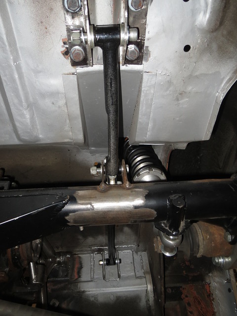
It soon became obvious that the existing way round that the Watt's linkages had been fitted didn't line up right so I had to take both linkages out and turn the pivots round as they are fitted with an offset. With them offset the other way, all was well and the links lined up centrally within their brackets, just as I had hoped and planned.

Image

So this was the point I'd been hoping for for some time. The rear suspension is now complete! And whilst the brakes still need sorting at some point, they can wait for now. Since it is now sorted, I could bolt the rear wheels on and lower the car to the floor. And it does now feel like a car, not just a shell or chassis. Although it did take me ages to gradually lower it down as I hadn't realised that the centre of balance is now just about level with the rear bulkhead. So trying to lift the car up to remove the stands just made it pivot the wrong way, which was a little risky when working on my own late of an evening. Finally it was down and roughly levelled, although I will need to do it again as I need the wheels to start the front suspension.

Image

Image

The car now feels a lot smaller, as it's no longer sat so far off the floor. It's good, but also a little odd still, seeing it with wheels. I'm just glad the ride height looks about right and when bouncing it up and down there's no creaks or groans and the springs even feel about right. But I suspect that will change once it's at kerb weight and being hustled down a back road. I also seem to have a reasonable amount of wheel clearance, but I need someone to bounce the car whilst I lie under it to check that more thoroughly.

So finally, it's now a wheelbarrow!!

Saturday, 18 October 2014

More flue fitting

On Thursday, rather than spending the day playing in the garage, I spent the day playing on a mate's roof. As he's not overly comfortable with heights, and lives in a 4 storey house, there was no way in hell that he'd be willing to climb up the scaffolding and sit on the chimney. The scaffolding was there as the lunatic had spent two weeks off work re-pointing the gable end. And being a tall house, there was a lot of it to do!! He's not ordered a stove yet, as we'll have to sort the hearth out with Building Control first as it's on the first floor. This means there's no concrete slab to use as a nice base, just the wooden joists.

So Thursday arrived, and up the scaffold we went. The plan was to fit the liner to one of his two chimneys and matching cowls to both pots. There was 12 metres of liner to fit, leaving plenty left over for trimming back later on when we fit the stove. This is the view from the top, and why I'm glad we only have two cowls to fit as they're £50+ each. Some of the neighbours have five pots!


The first thing to do was to make sure we could drop a pull rope down the chimney and to the correct fireplace. The chimney we're lining has at least two fireplaces, so a set of drain rods were pushed up so we could tie the rope off before pulling it back down. This is much easier than just hoping for the best!

Or, it would have been if the rods went all the way up the chimney. But they jammed about 7-8 feet down from the pot. And looking into it (something I really should have done first) revealed what looked like a plate of some sort. As it was so far down, we couldn't figure out what it was, or why it was there. It felt solid enough that we thought it was a plate with some loose debris on top of it.


As we thought it was solid, the only option was to remove it from the stack. And the only real way of doing that is to take some bricks out. Which revealed something different what we had expected. Due to being left open, the chimney had acquired a bird's nest at some point, which had then fallen in and jammed at the first bend. There was a total of 18" solid of old bird's nest, sticks and what not in there!


So now we knew the chimney was clear and we could get a pull rope all the way back down to the fireplace. My mate had also stopped panicking at this point. One thing making this all a little easier was the external soot door that his house has. This means less climbing all the way down the scaffold, into the house and back up again as we can just shout at each other through the hole. It will also mean that there's no need to work inside a tight chimney from below as the final joints can be done through the door.

Part of the difficulty in fitting a liner is dealing with 12 metres of coiled up tube whilst so far off the floor. It's too long to do by yourself and too heavy to sling around easily. But that's what mate's girlfriends are for! This is also further proof that there is nothing you can't do with enough insulation tape.


I wasn't able to take photos for a little while after this point as I was sat between the chimney pots shoving the liner in. But the next point was fitting the cowl to the liner and then the cowl to the pot. Whilst there was no need to fit a second cowl, the other chimney had slugs in it from where it has damp, so something to keep the worst of the rain and the birds out was a sensible idea whilst we had access. The second chimney will also be swept soon as well.


And that was it for working outside. We then moved into the house and started knocking the fireplace apart:


And that's the limit of progress for now, as the happy couple are off on holiday! We're not sure what's been done to the fireplace in the past, but there's clearly an additional set of bricks on the left, but without them the arch wouldn't be supported. Which makes little or no sense. Either way, the plan is to remove the new bricks and fit a lintel before doing much else. I'll report back when I'm next allowed near his house with a hammer. Assuming his girlfriend hasn't knocked it down first. She's an architect and a nutter with a hammer in hand.

Friday, 17 October 2014

A new approach to the support

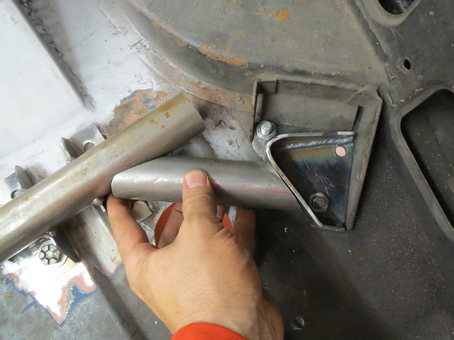
Following my frustration at not being able to make the piece of 1.5" tubing fit between the cross brace and the chassis mount, I spent quite a while doing a Google image search for ideas or options I hadn't thought of. And one thing I had thought of but had discounted soon became apparent. I had thought of using a vertical section of tube to mount the short piece of tube to, but I didn't much like this idea. The option I had discounted involved using a vertical strip to run round the mounting plate and to then weld the tube to that. This seemed like a more versatile idea, one that be easier to make and look like better once done.

So I set about marking the plates for where I thought it best to put the strip and therefore the loads. This gave the best compromise between leading straight off the short section of tube and allowing room to fit the captive nuts later on.
Image

It was then on with cutting a 3mm strip overlength so I could trim it back and not risk screwing up the bends. Once I was happy with the shape, it was welded on. The sides were then cut with a slight taper and the sharp corners rounded off too.
Image

Image

Image

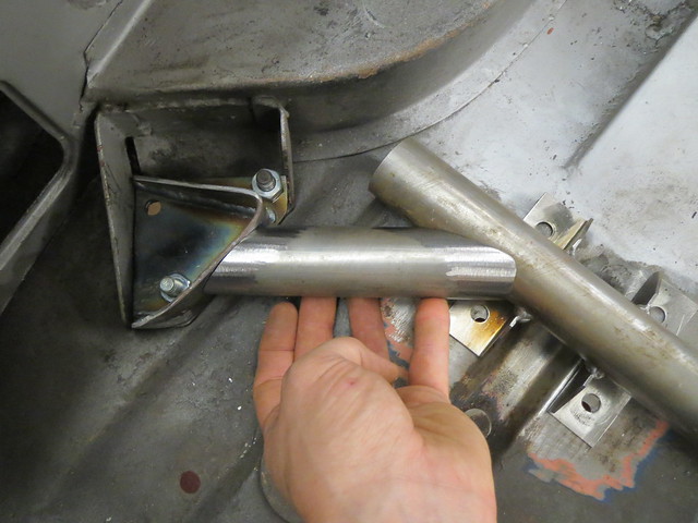
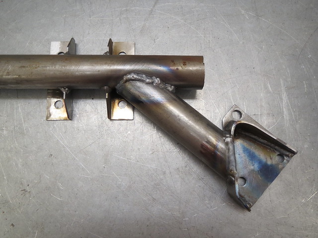
With the chassis plate now in place, I managed to find an off cut of tube with just about the right shaped cut on it. This was fitted properly and then a copy was made before I tacked the right hand piece in place. Once tacked, it was removed for welding on the bench. If I were to make this again, I'd probably weld the tubes together and then fit the feet as I can't quite fully weld the left hand side of the joining section. Given the large weld area it won't matter, but it annoys me a little bit that it's not complete.

Image

Image

Once I have the other end welded on, I will cut the excess tube off and probably cap the ends as I saved the cut outs from when I cut the feet brackets. Once I get the tube complete I can then finally get rear wheels on. I had planned on doing this earlier in the week, but everything seems to have taken so much longer than expected. Hell, even helping a mate fit a flue liner on Wednesday involved pulling bricks out the top of the chimney 3 floors up!

Thursday, 16 October 2014

Wednesday's update, but a frustrating day

Nothing to update from today, but there is an update of sorts for Wednesday.

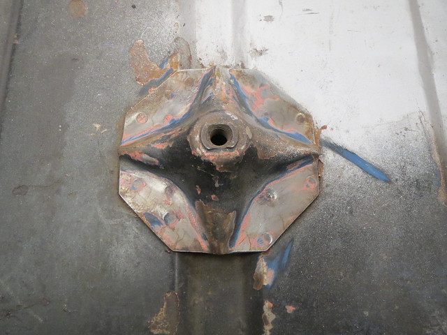
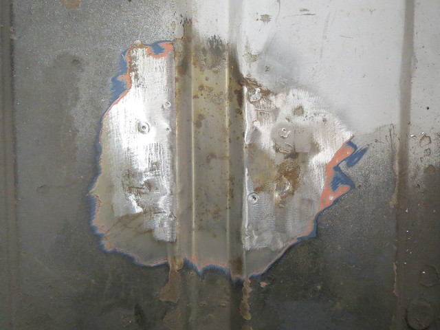
The aim for Wednesday was to sort out the Watt's link support in the boot. The first thing to do was to remove the spare wheel support. Thankfully, this is just twelve spot welds to drill out.


And that now gave room for me to start planning out how to actually fit the mount and what it should look like. I figured there were two main options: weld in a brace bar or sort a bolt in version. Weld in is stronger, but removes the ability to easily repair it in the future and it would be harder to fit. A bolt in version would be replaceable but possibly much harder to make. I went for bolt in in the end as it gave me the ability to mess it up and re-do it if need be.

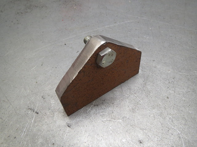
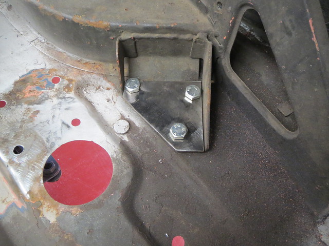
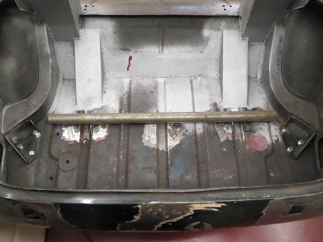
The first thing to do was to cut a pair of plates to fit to both of the rear spring hangers. These would be the mounting points for the brace. Although the photo shows the bolts pointing down, the final version will have captive nuts on the plates to reduce the amount of metal sticking out into the wheel arch.


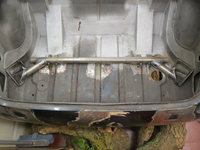
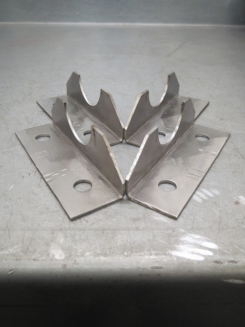
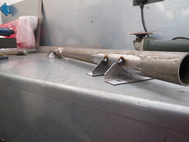
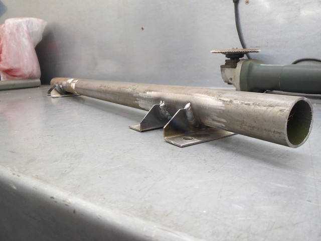
Then it was on with the cross bar and the mounting feet for the Watt's brackets that hang under the car. These needed to be a good close fit to the 1.5" brace tube, but also be wide enough to provide a wide mounting plate. This is what the final design looks like.


Four of these were then cut out in steel and drilled.


Using the existing mounting holes as a guide, these were then trial fitted to the shell before being tacked in place. The brace was then fully welded on the bench to ensure all four brackets were flat and straight.


Some of the mounting holes that I drilled before will need welding up and re-drilling now that I have a straight set of mounting points to aim for. But this won't take too long to do. The bit that did take quite a while, and even then I binned my last attempt, was to figure out a sensible way to join the cross brace to the spring hanger plate. What I was trying to do was to see if I could shape a short bit of the 1.5" tube to both meet the cross brace and still provide a good wide weld footprint on the plate.

After a good while of trying to get the two to meet I gave up. I just couldn't find a way make the shallow angle between the short tube and the plate work out. I think I will end up having to either use another short vertical section of tube to make the angle flat, which will look like the cups I have been using, or I will need to use two bits of maybe 1" tube to make a triangle between the plate, the end of the tube and the mounting feet. I have some 25mm x 3mm wall tube that would do well for this. I'm not sure which of the two options will be best. More thought will be required before I do either option.